Magnetic Fluid Control System for Drug Therapy

Magnetic Fluid Control System for Drug Therapy

Timeline:
Fall 2018 - Spring 2019

Tools used:
SolidWorks, Python, Arduino

Background

Magnetic drug delivery focuses a cancer drug to a target area by coating a colloidal mixture of ferrofluid nanoparticles and a suspension fluid with therapeutic drugs, injecting the mixture into the body, and delivering it to the target area in vivo by manipulating an external magnetic field. While previous research has explored regarding the efficacy of magnetic drug delivery, little has been done to implement a control system that moves the ferrofluid to a specified location.
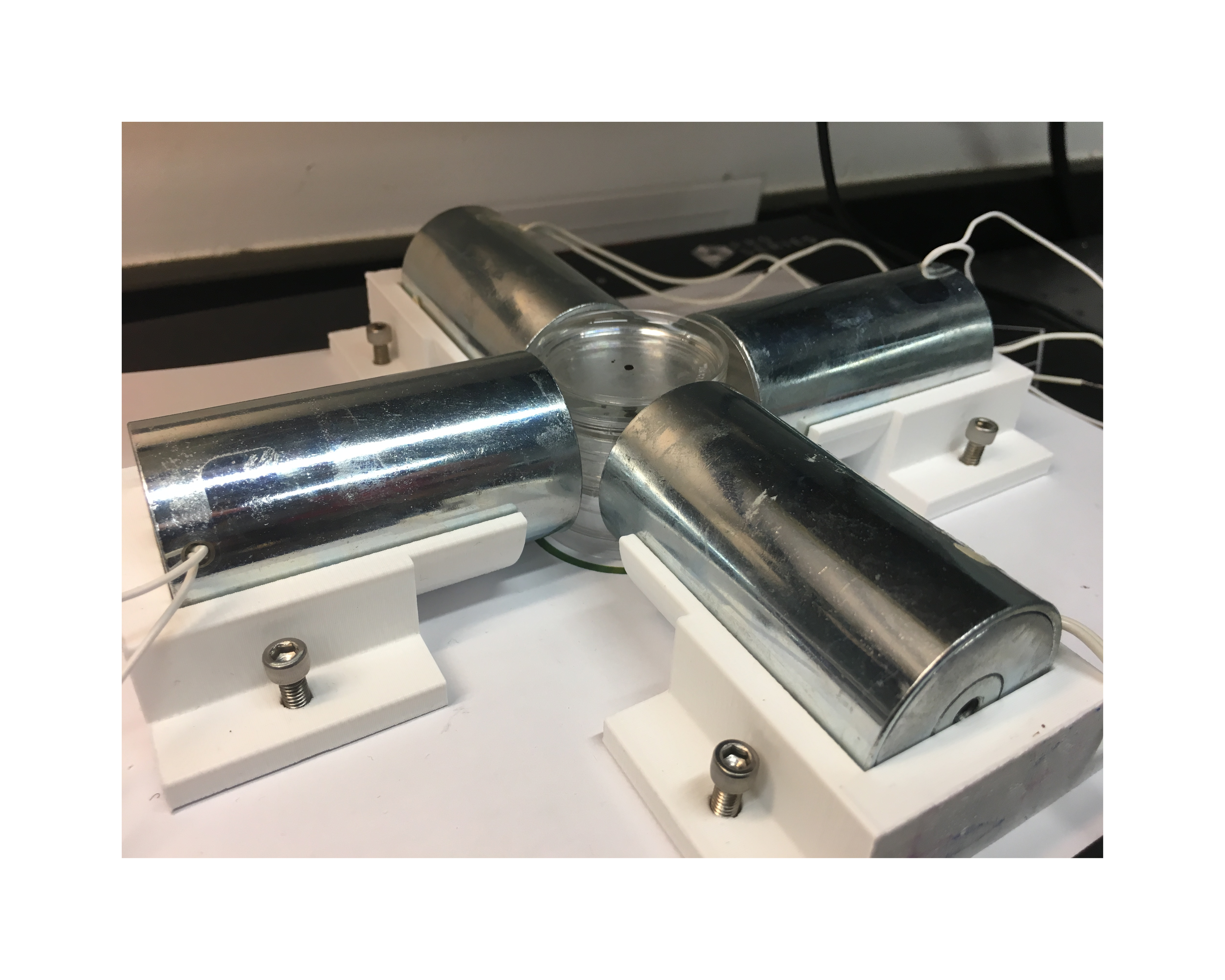
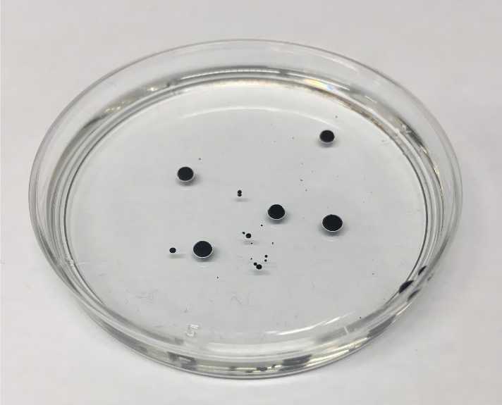
The goal of this project was to design a fully operational 2D ferrofluid particulate control system. I worked in a team of 3 to develop test rigs for the control system and to write Python/Arduino code that triangulated the position of a ferrofluid particulate using magnetometer feedback and actuated the magnetometers to minimize the required power to move this particulate to a desired position. By the project’s conclusion, we successfully controlled a ferrofluid particulate using visual feedback and developed an algorithm that can accurately determine a ferrofluid particulate’s position in real time without visual feedback by using a magnetometer array.

Material Selection

To simulate the ferrofluid and suspension fluid, we used EMG 304 (a water-based ferrofluid) and vegetable oil. The suspension fluid’s higher viscosity allowed the ferrofluid to retain its shape with minimal diffusion and move at relatively slow speeds for stable control.

We selected electromagnets based on the nominal magnetic strength, cost, and size. The magnetic field needed to be strong enough to pull a ferrofluid particulate while overcoming viscous resistance and without overheating. Based on preliminary research and basic magnetohydrodynamic simulations, we purchased 4 1.5-inch diameter electromagnets with 1687 turns each. These electromagnets had enough turns to generate a magnetic field throughout the intended control region while being small and inexpensive enough to fit well within our test rig and budget.

Magnetic Field Theoretical Model and Experimental Validation

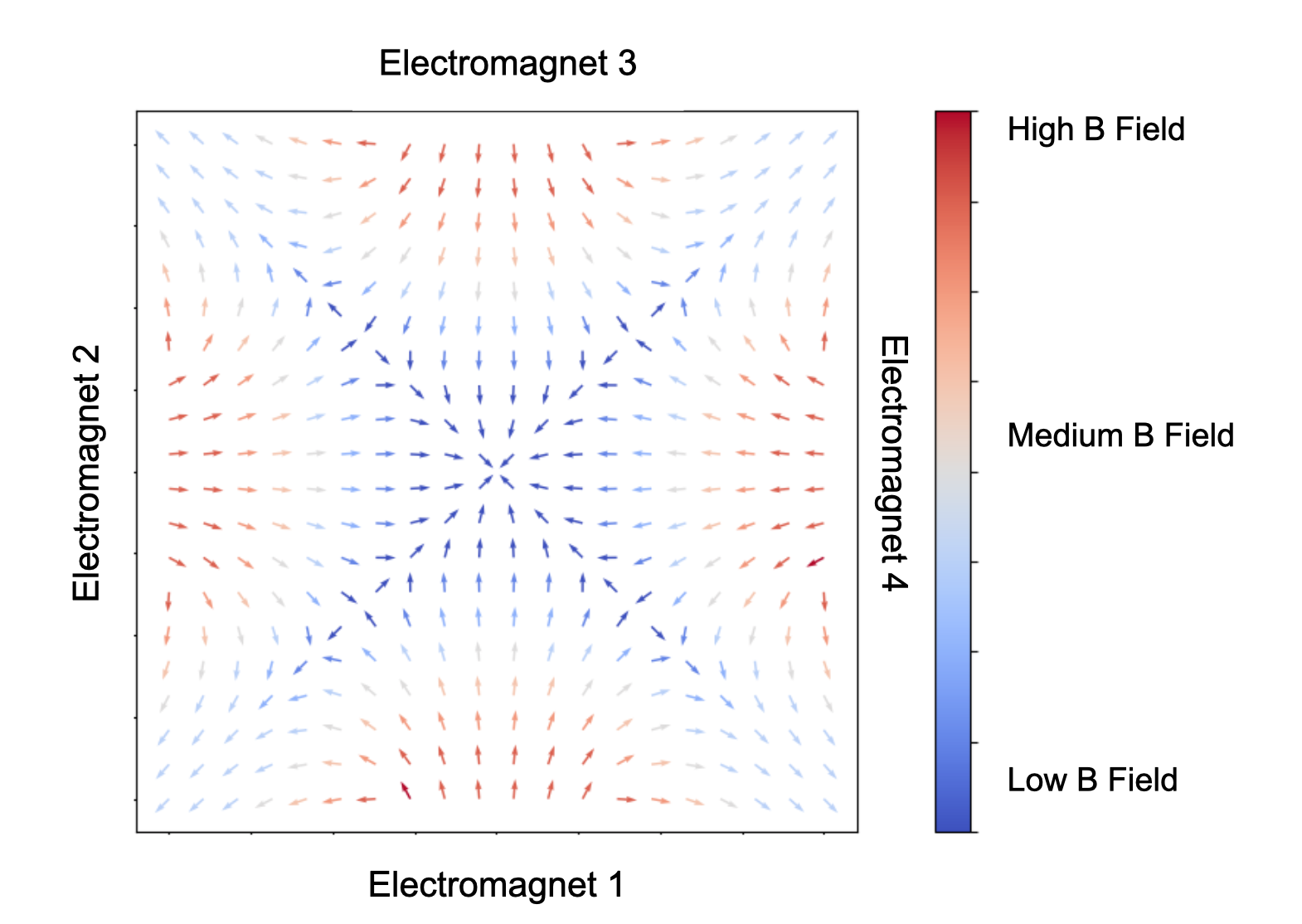
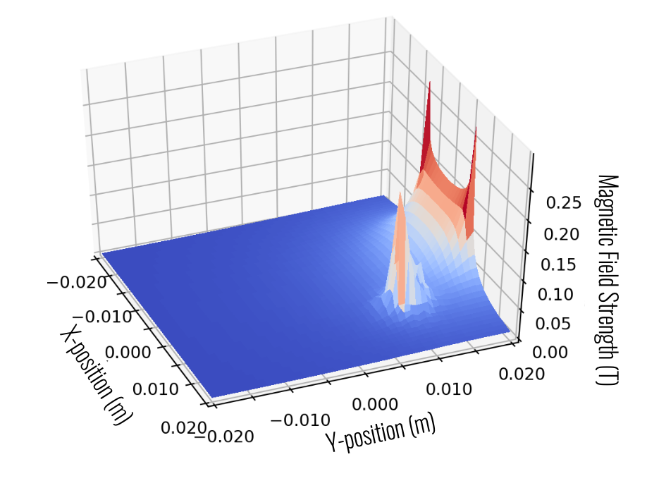
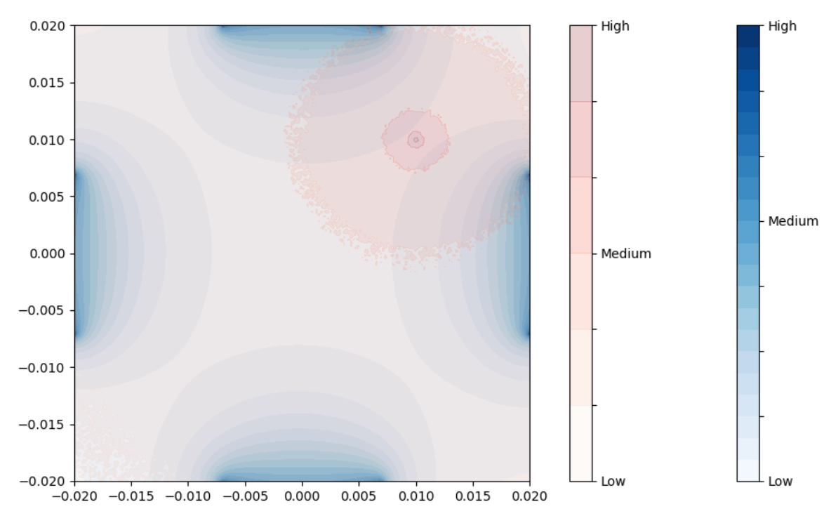
To predict how the ferrofluid would move under the influence of the electromagnets, we modeled the resulting magnetic field within a 2-centimeter radius Petri dish surrounded by 4 electromagnets placed axisymmetrically around the dish. The external magnetic field was characterized using Biot-Savart’s law.

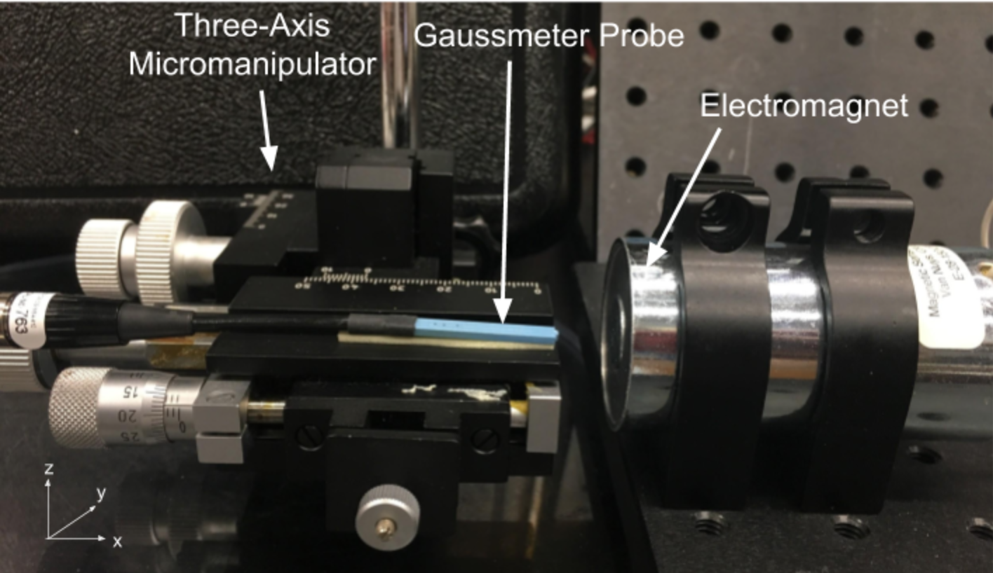
To physically validate the above results, we developed an experimental rig with one electromagnet, a Lakeshore 410 gaussmeter connected to a Hall probe, and a three-axis micromanipulator to hold the probe and accurately change its position in 3D space. As the probe moves around the electromagnet, it measured the magnetic field output in real time; these data points were recorded for comparison to analytical results.

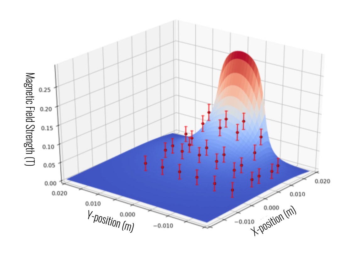
We produced an analytical surface plot of the magnetic field produced by a single electromagnet overlaid with experimentally measured points for validation. The positions of the data points had uncertainty in the x and y directions representative of the instrumental uncertainty of the micromanipulator, and the magnitude of the magnetic field had uncertainty due to both the micromanipulator and the gaussmeter. The error bars shown below represent the larger of the instrumental and experimental errors.

Tracking Algorithm

We implemented a least squares error minimization optimizer to minimize the error between the recorded magnetic field and a simulated magnetic field within the control domain. This minimum error approximates the position of a magnetic particle within the region. We place positional constraints to keep the magnetic particle’s position within the Petri dish and magnetization constraints to ensure that the particle’s orientation does not affect its computed position.

Our tracking algorithm took advantage of the nonlinear nature of the magnetic fields to minimize error, time, and power exerted on electromagnets. The controller was split into 3 segments: a linear segment to scale the error between the current and desired ferrofluid position using an experimentally-determined proportional gain, a nonlinear segment to determine the voltage needed for each electromagnet to achieve the desired magnetic field, and a nonlinear filter to ensure smooth voltage and magnetic field changes as the ferrofluid travels along its calculated path.

Visual Feedback Control Setup and Demonstration

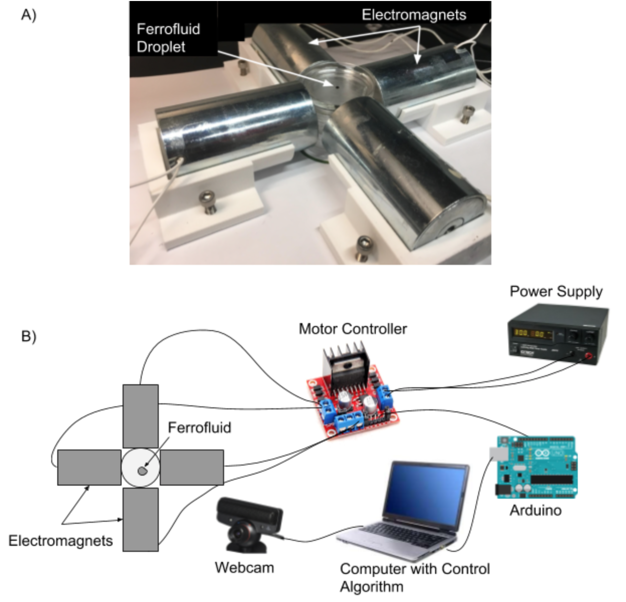
We developed a visual tracking setup to directly compare to a magnetometer array setup. This visual tracking setup was able to move a ferrofluid particulate in the Petri dish to a desired point in 2D space. A webcam relayed the current position of the ferrofluid to our control algorithm, which output 4 voltage commands to the Arduino. The Arduino sent a PWM signal to the L298N dual H-bridge motor controller to control the effective voltage given to each electromagnet.

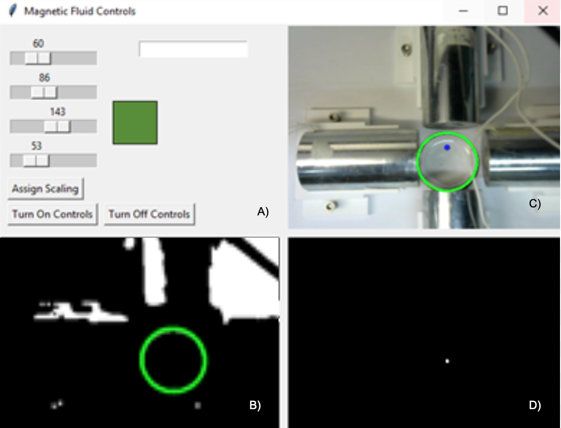
The visual feedback system used a Logitech C270 webcam and Python’s OpenCV library. The webcam 720p resolution was sufficient to track a particle moving at speeds on the order of 1 mm/s. We wrote a Python script with a tkinter GUI to search for the boundary of the Petri dish (represented by a thick green circle), ignore all images outside of that boundary, and locate the ferrofluid particulate within the control domain.

The control algorithm demonstrated precise and quick control of the ferrofluid, consistently moving it to the desired setpoint.

Magnetometer Array Control Setup and Demonstration

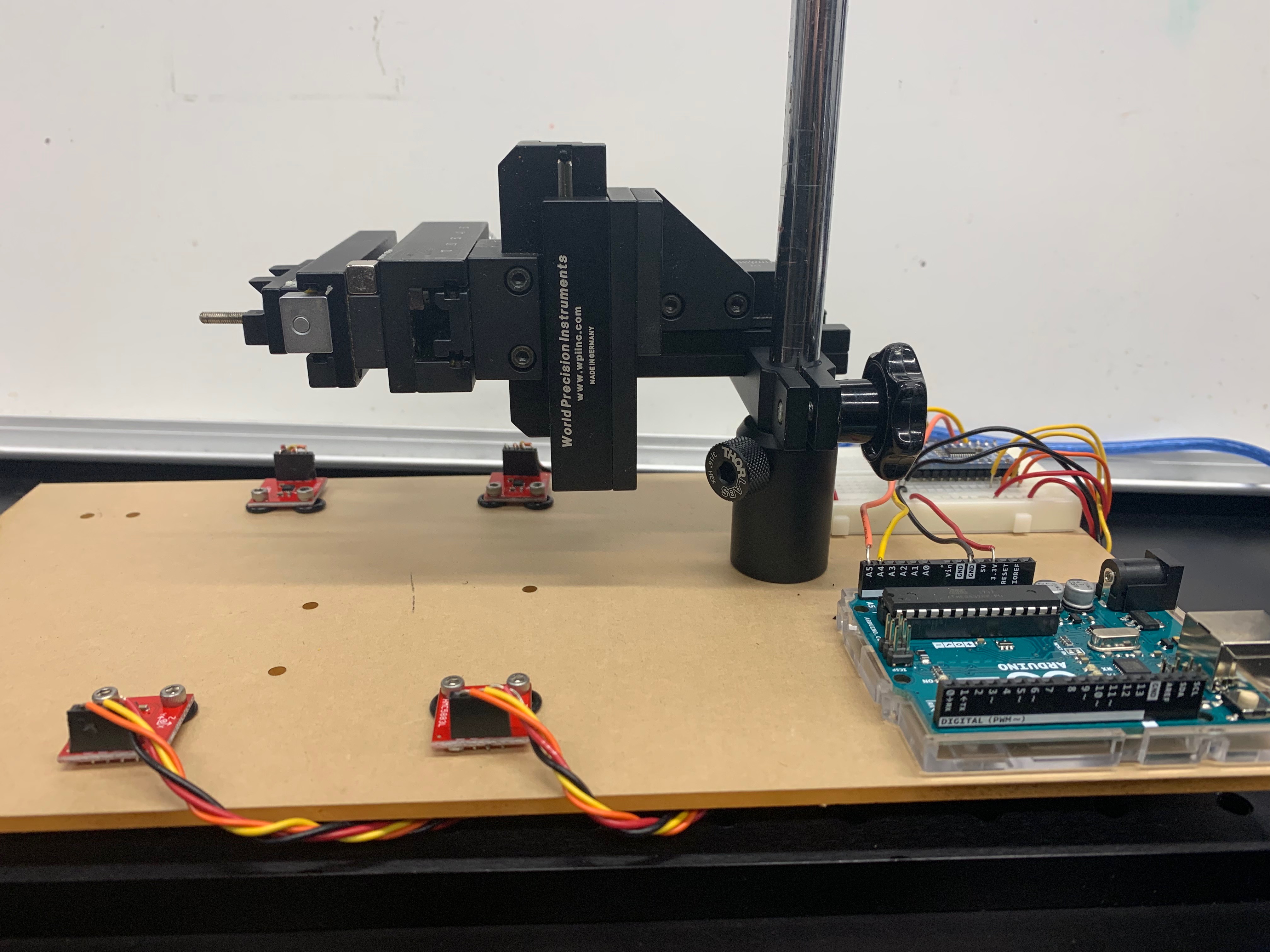
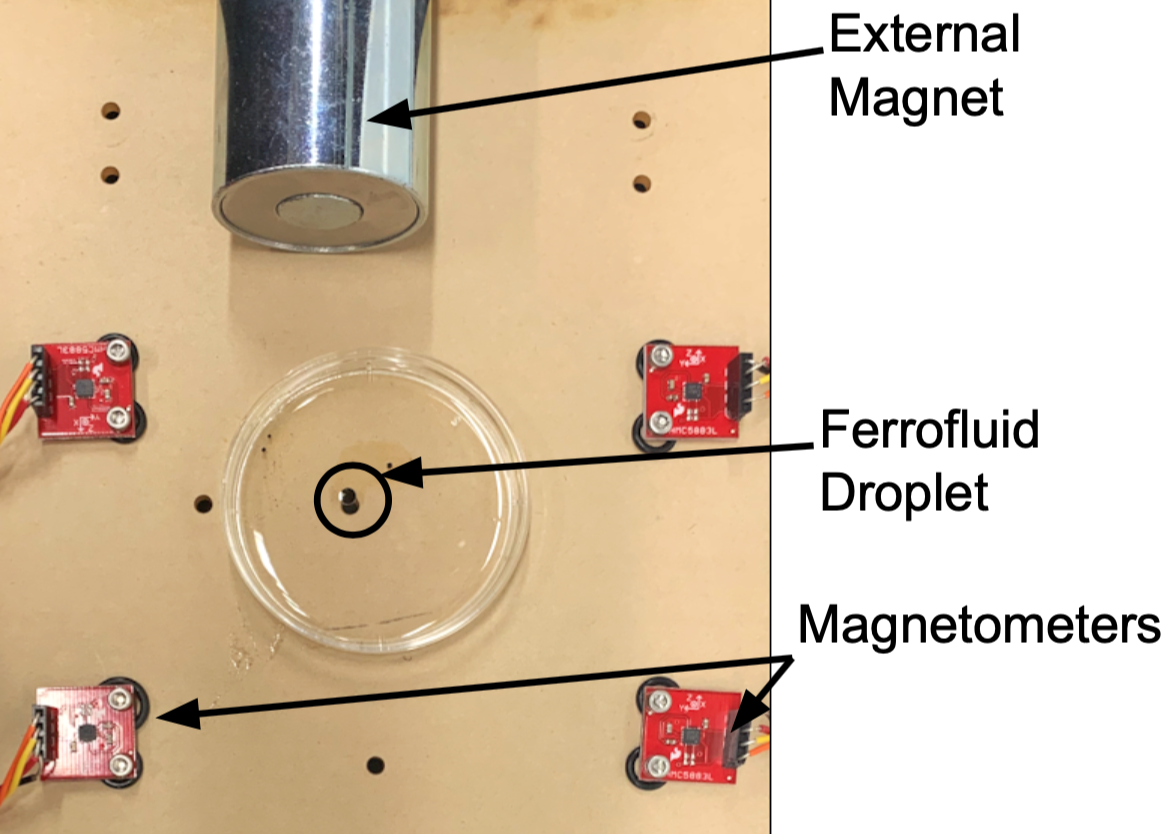
The experimental rig for the magnetometer array consisted of 4 MAG 3110 3-axis magnetometers, a 3-axis micromanipulator, an Arduino microcontroller, and an electromagnet. The localization algorithm only required 3 magnetometers to fully locate a magnetic object; 4 magnetometers were used in this configuration for more accurate tracking.

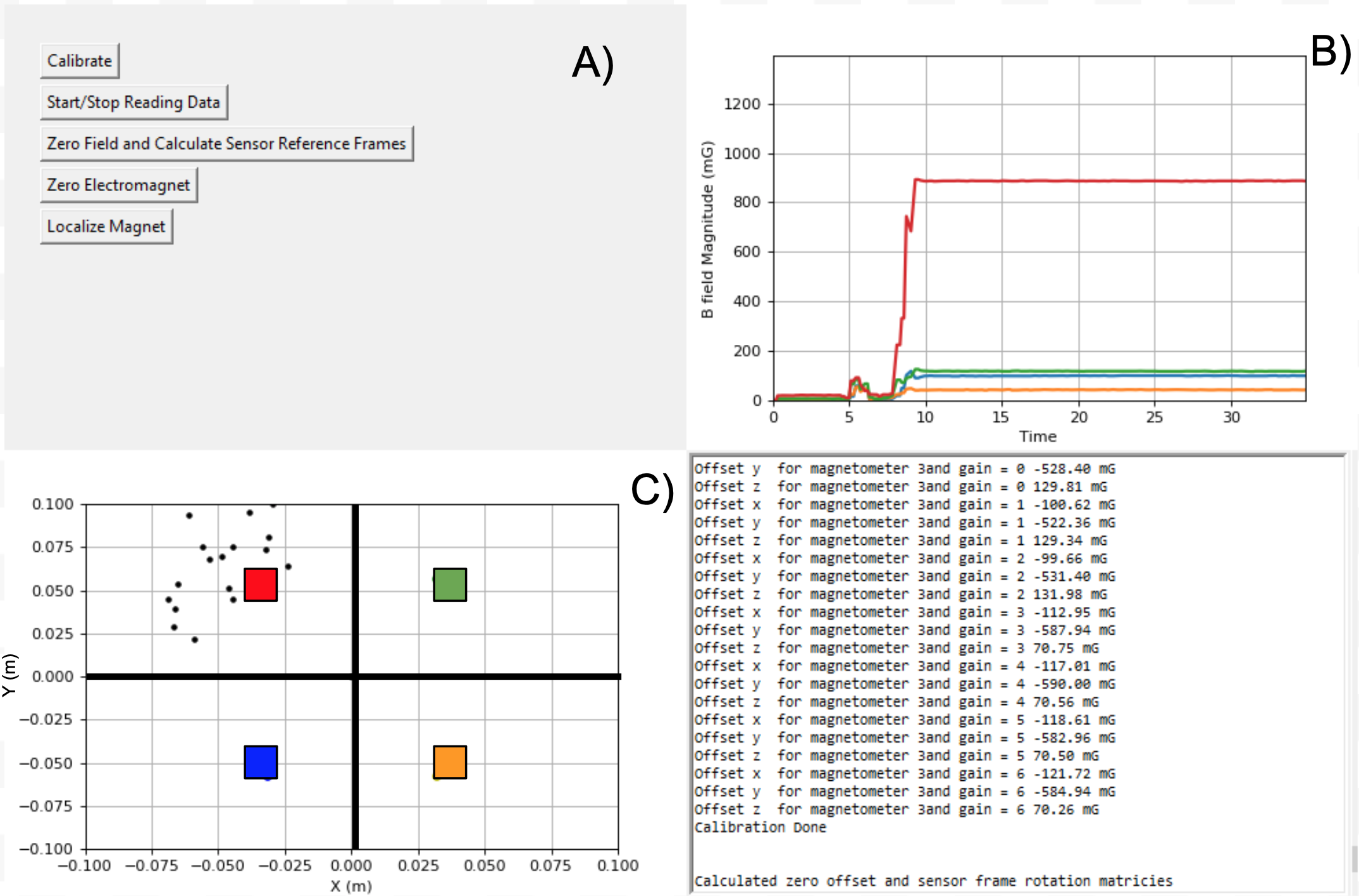
We created a tkinter GUI in Python to display data recorded from the magnetometers and the calculated position on an XY plane. The magnetometers were color coded for easy distinction. To mitigate soft-iron distortions, we determined appropriate offset factors by rotating the entire setup on a turntable while the magnetometers output their minimum and maximum magnetic field readings. Each recording was offset by a constant amount until the maxima and minima match. When this was achieved, all magnetometers read roughly the same value under Earth’s magnetic field in any orientation, indicating successful calibration. A Bluetooth connection prevented wiring issues while rotating the setup.

After calibration, Earth’s magnetic field was uniformly subtracted from each magnetometer, rotation matrices converted the magnetic field readings from the magnetometers’ reference frames to a common reference frame, and the position of the ferrofluid particulate was determined using a simple triangulation algorithm.

Using the same control algorithm described above, we derived the position of the ferrofluid and successfully moved it in 2D space without visual feedback.

A 52-page report further detailing the motivation, operating metrics, reasoning for material selection, and algorithm descriptions can be found here.