Heat Exchanger Design and CFD Analysis

Heat Exchanger Design and CFD Analysis

Timeline:
Spring 2018

Tools used:
ANSYS Fluent, SolidWorks, Excel

Background

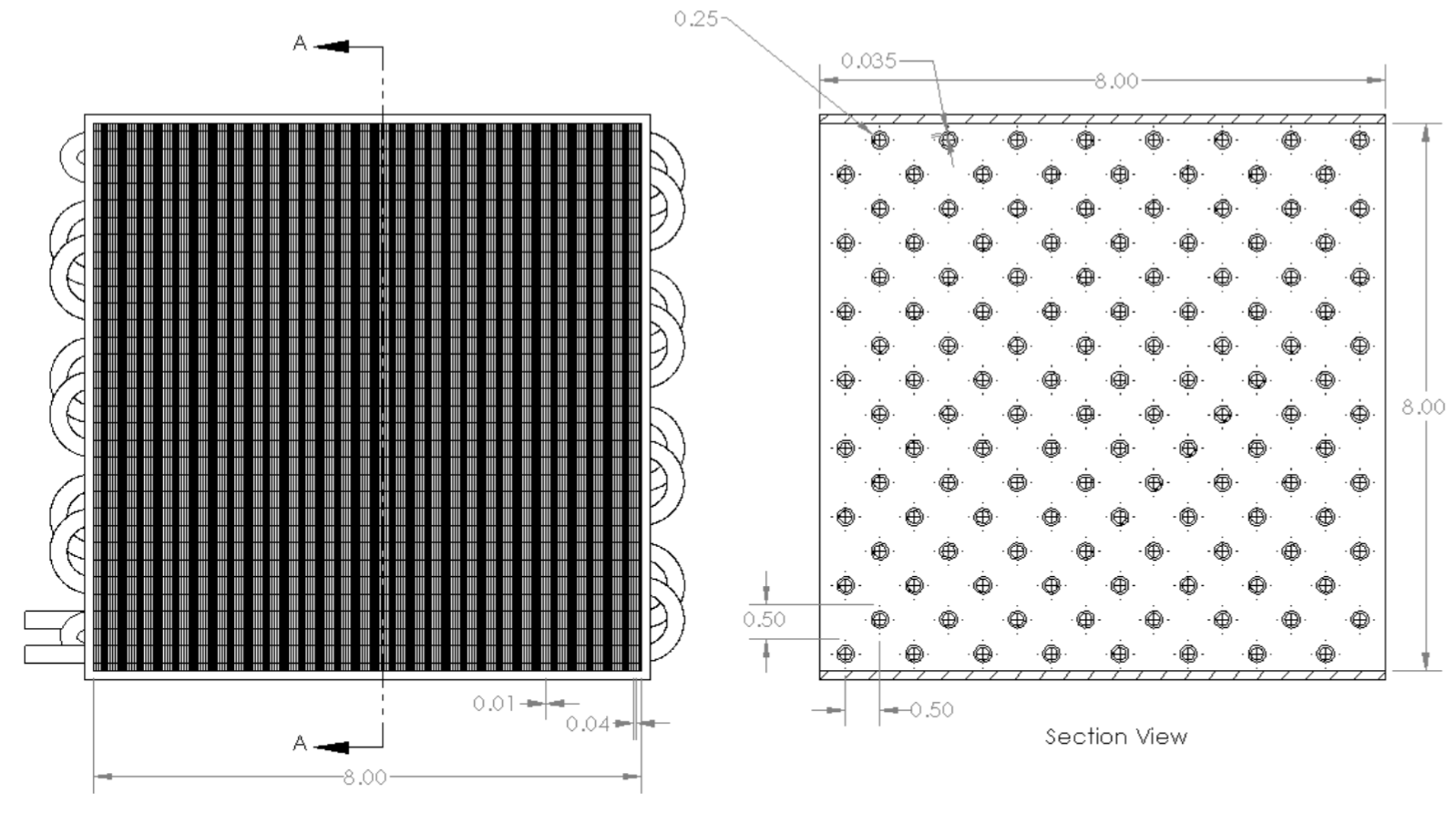
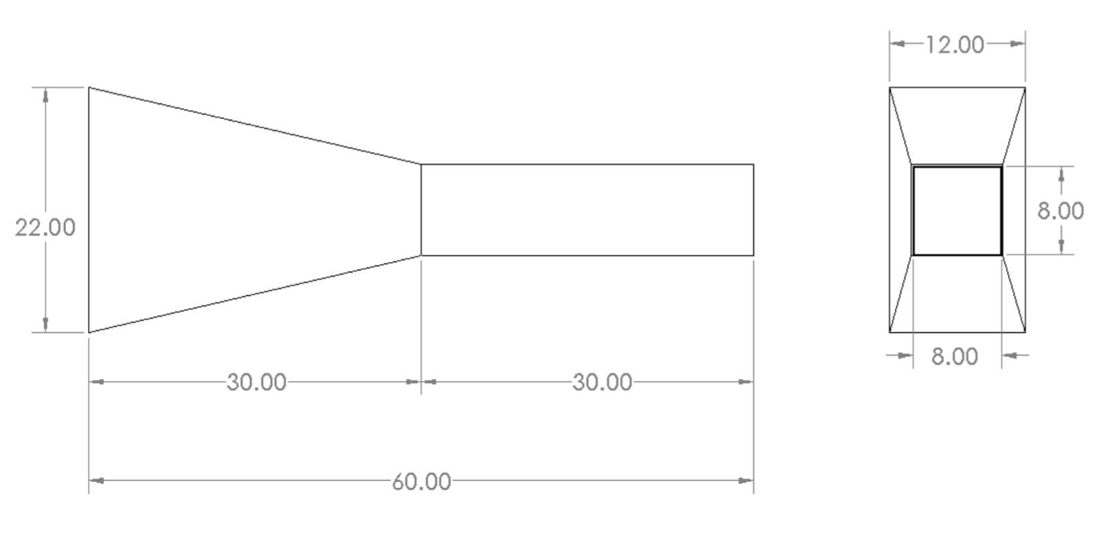
For the midterm project in Cooper Union’s Computational Fluid Dynamics (CFD) course, the class was divided into 4-person teams tasked with designing an automotive heat exchanger under specified temperature and velocity constraints. The objective was to minimize the size and dry weight of the heat exchanger while reducing the engine oil temperature from 350°F to a maximum of 195°F. The incoming air temperature was 108°F, and the oil flow rate ranged from 3.5 to 5.5 gpm, with the vehicle moving at 25 mph. The air was delivered via a duct mounted 60 inches upstream of the heat exchanger; the design of the duct aside from its inlet area was also to be designed. No constraints are placed on material compatibility or pressure drops for air or oil across the heat exchanger aside from standard engineering assumptions in line with existing automotive heat exchangers. We performed a set of steady-state CFD simulations and validation hand calculations to carry out this design task.
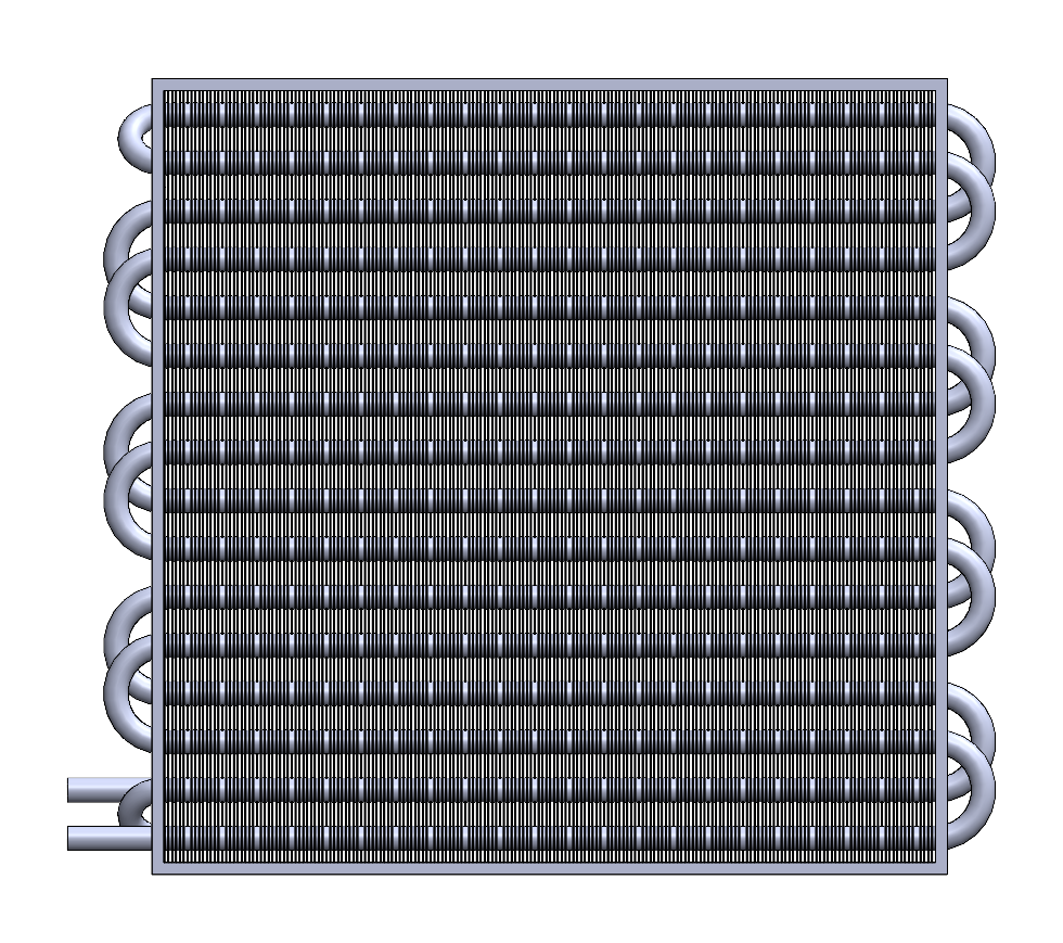
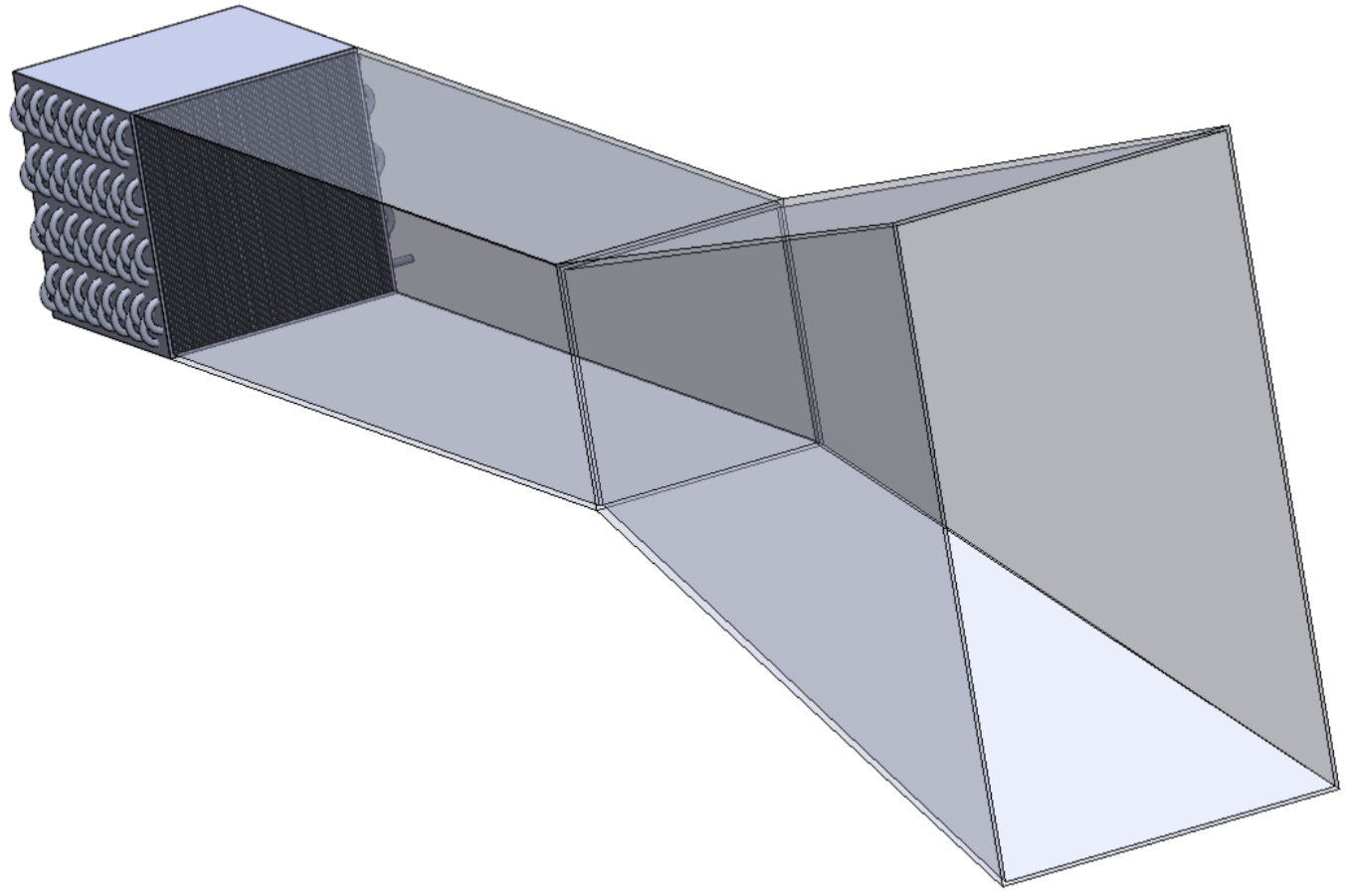
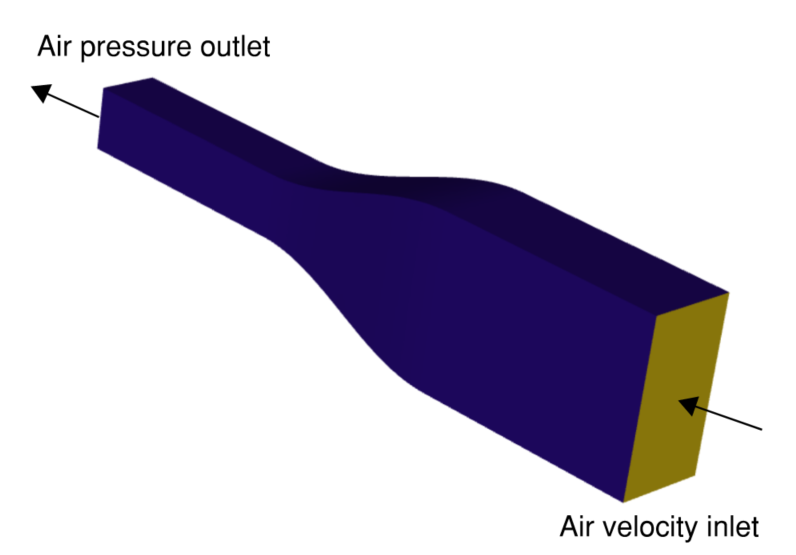
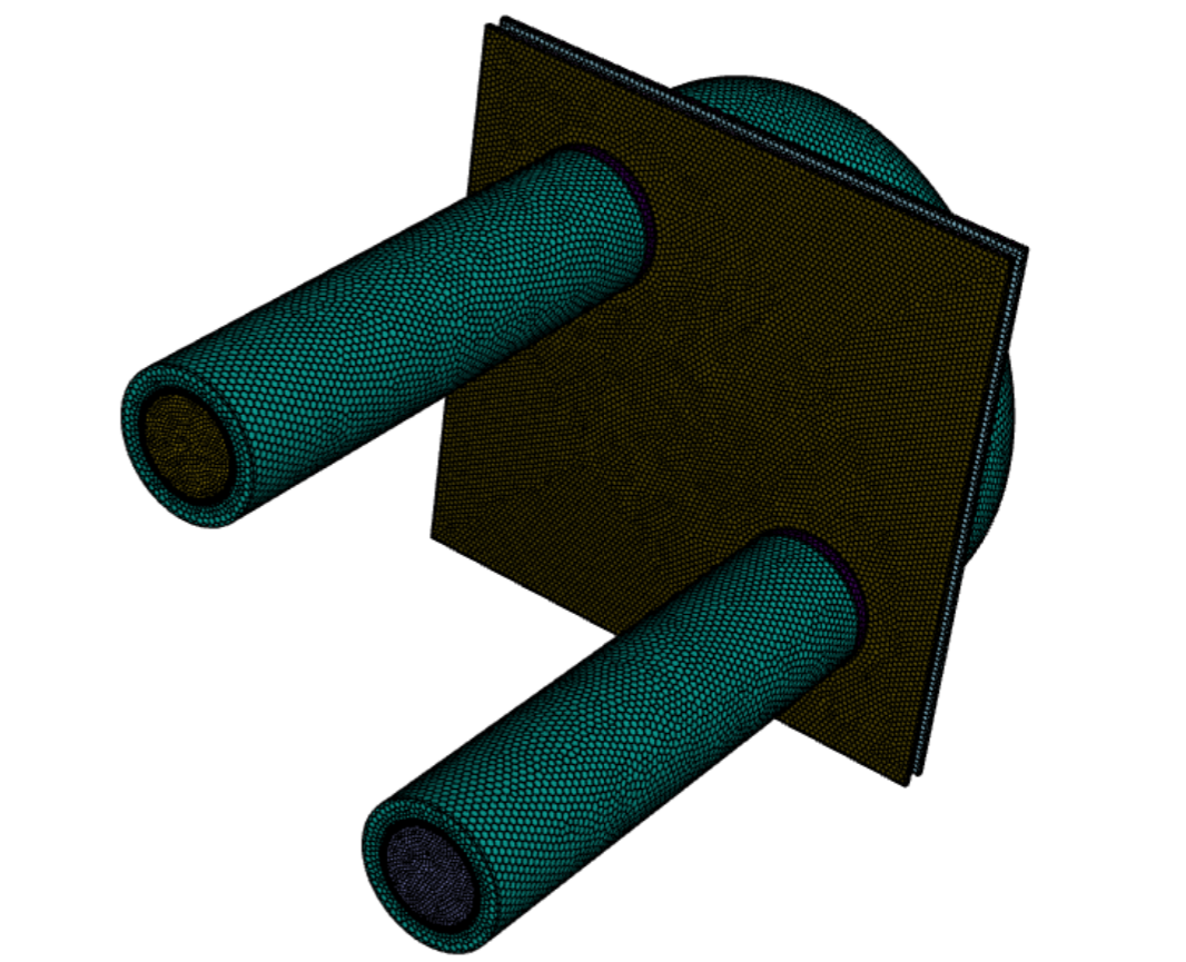
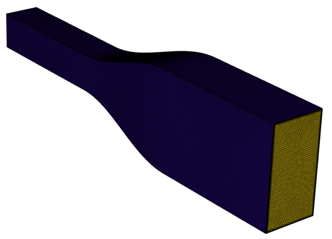
Image related to paragraph 0 Heat exchanger and duct geometry.

Each team was given the same design limitations, performance criteria, and design goals. The full assignment can be found here.

Design Concept

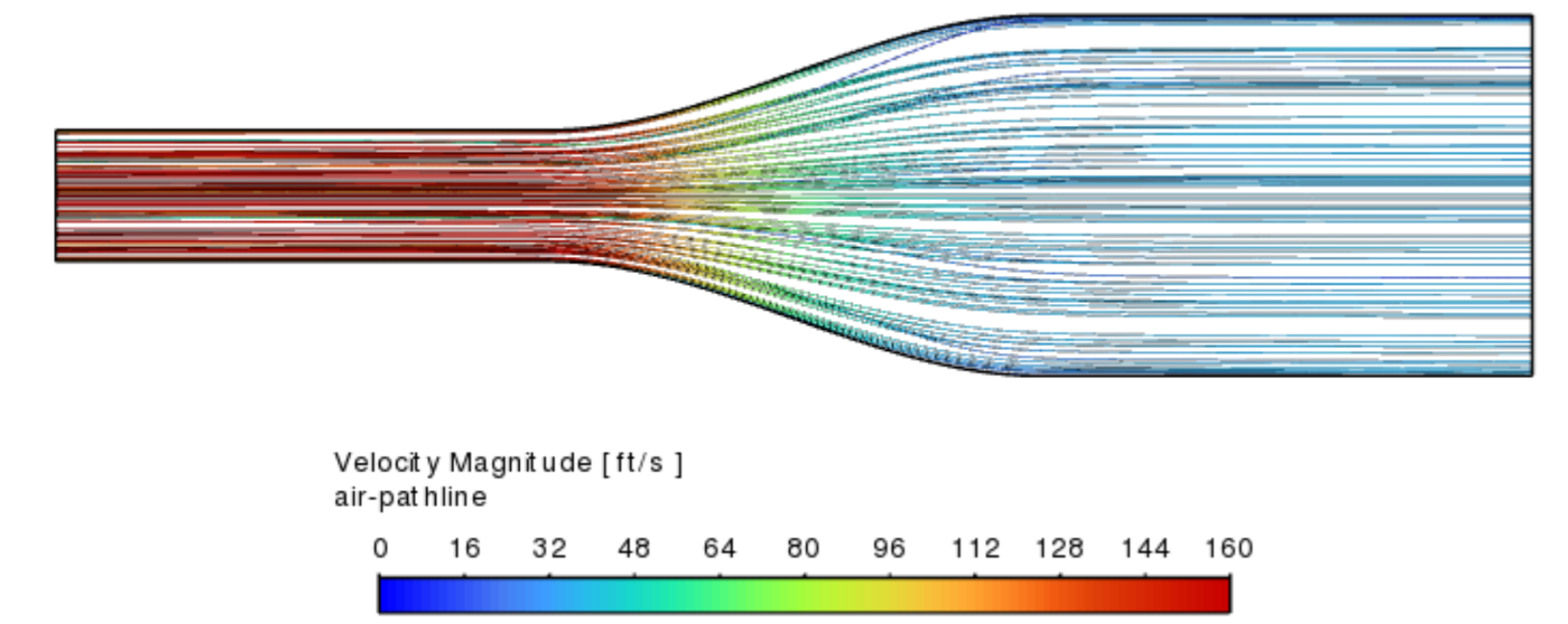
Based on existing automotive heat exchanger designs, we chose a finned crossflow heat exchanger with a staggered tube bank and with both fluids unmixed. Copper was selected for the heat exchanger tubes due to its high thermal conductivity, while 6061 aluminum was chosen for the duct for its low density and adequate thermal conductivity. We neglected radiative effects in both hand calculations and simulations based on preliminary hand calculations indicating that radiative effects were very small compared to forced convection. The heat exchanger duct transitioned smoothly along its 60” length from the required 22” x 12” cross section to the 8” x 8” inlet area of the heat exchanger.

Design Hand Calculations

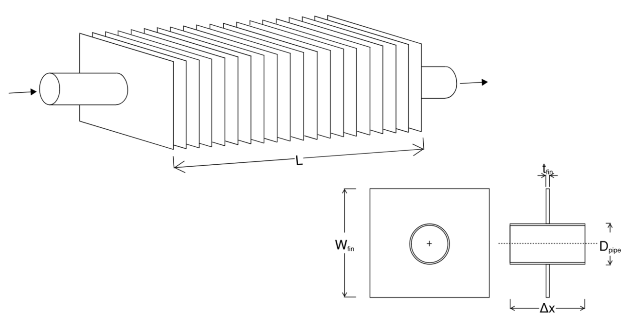
The design hand calculations simplified the heat exchanger into a long straight tube with rectangular fins surrounding the tube perimeter. This approach allowed us to evaluate the impact of geometric parameter changes on the heat exchanger’s overall size and dry weight, simplifying the problem into a multidimensional optimization problem. Excel’s Solver tool was used to optimize parameters and visualize how changes affected the heat exchanger’s size, weight, and performance metrics.

Heat exchanger simplified geometry Heat exchanger simplified geometry.
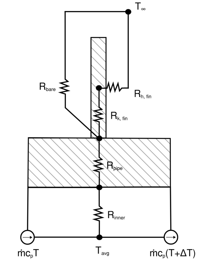
We calculated convection coefficients for oil flow inside the tube using the Dittus-Boelter equation, for air flow across the bare tube using a Nusselt number correlation for flow over a cylinder, and for air flow along the fins using a Nusselt number correlation for flow along a flat plate. These coefficients were used to construct a thermal resistance network based on the simplified geometry, allowing us to calculate the number of fins, heat exchanger size, and dry weight required to meet the temperature and flow rate criteria.

CFD Simulation Setup and Mesh

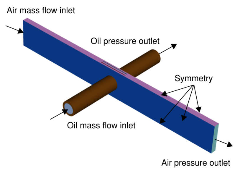
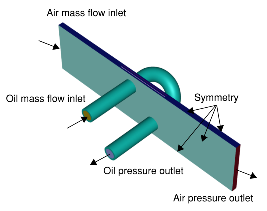
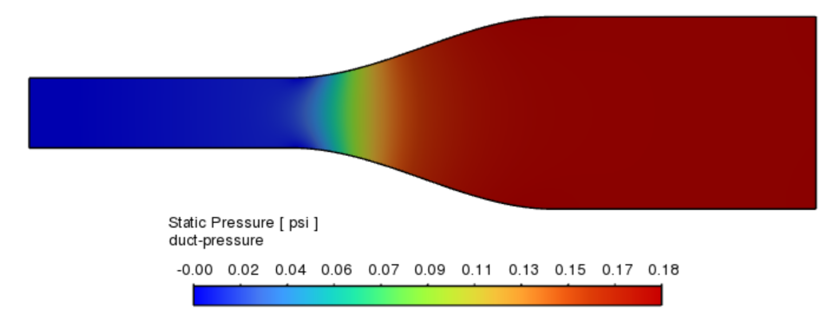
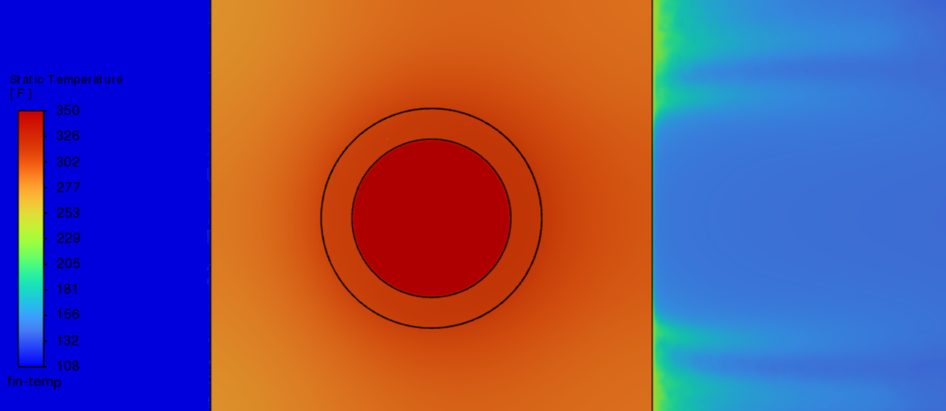
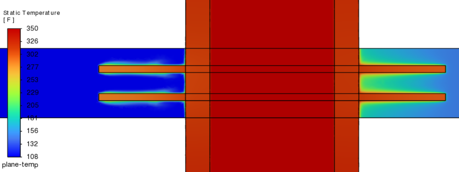
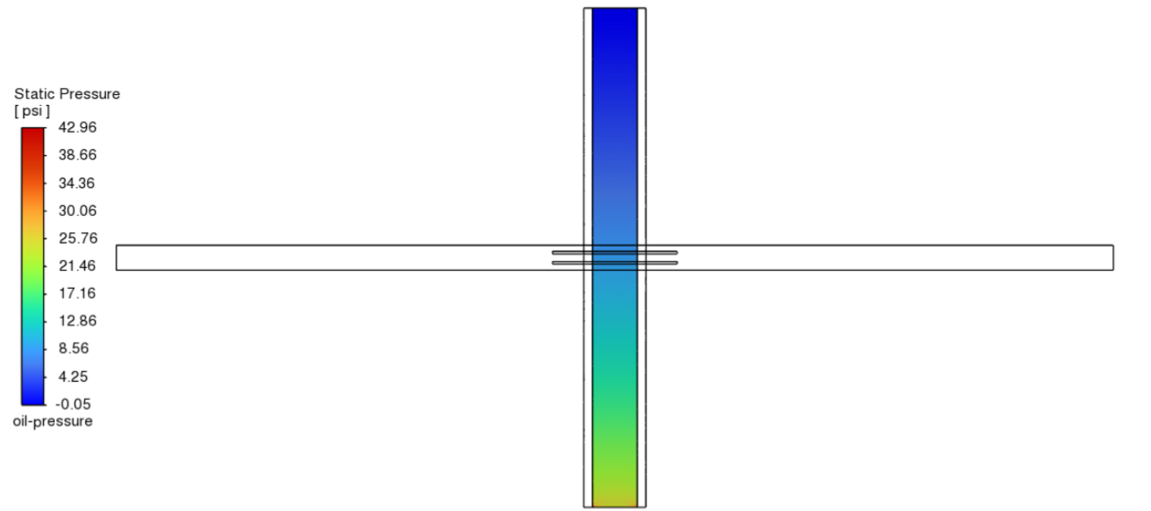
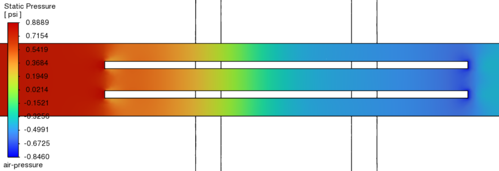
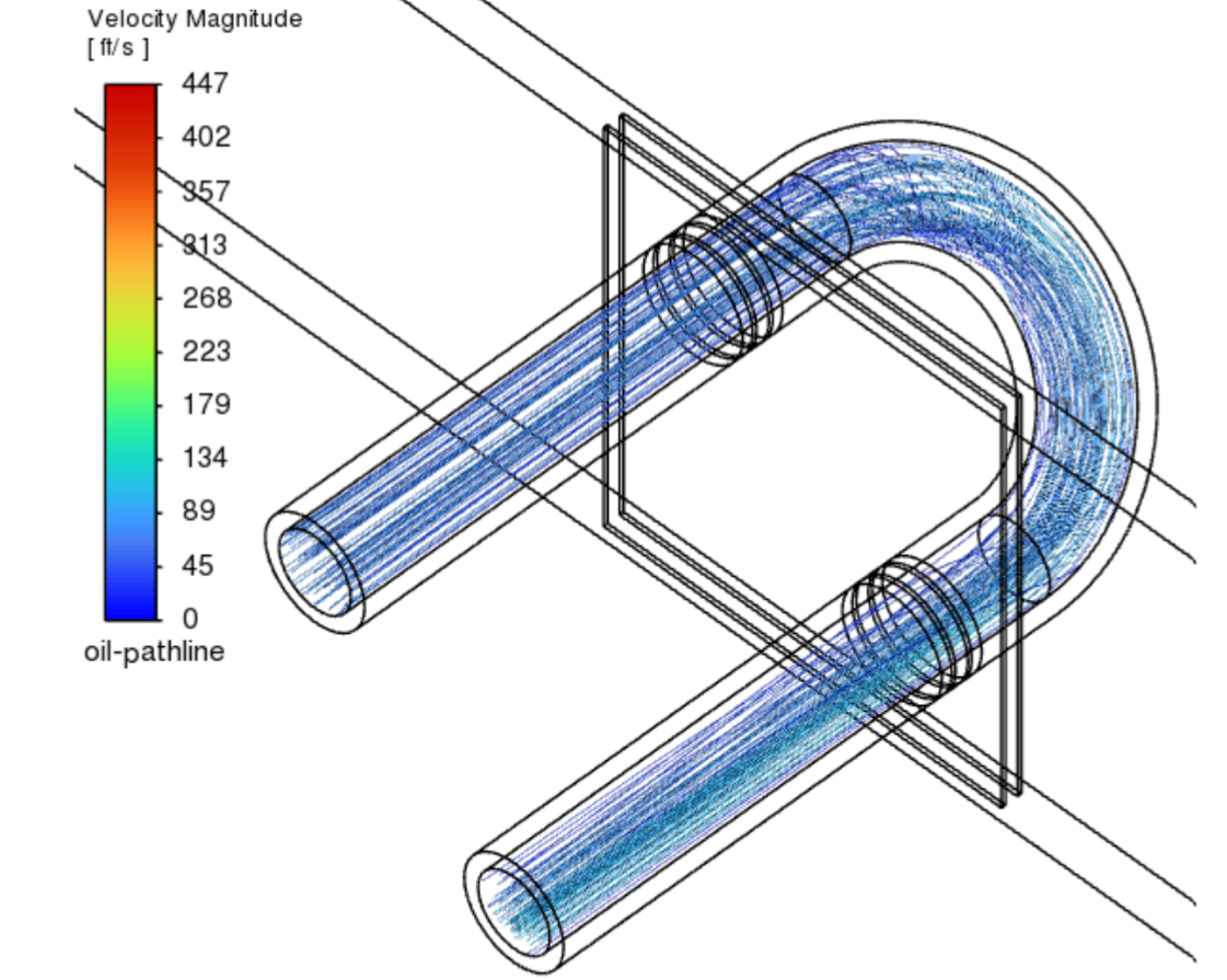
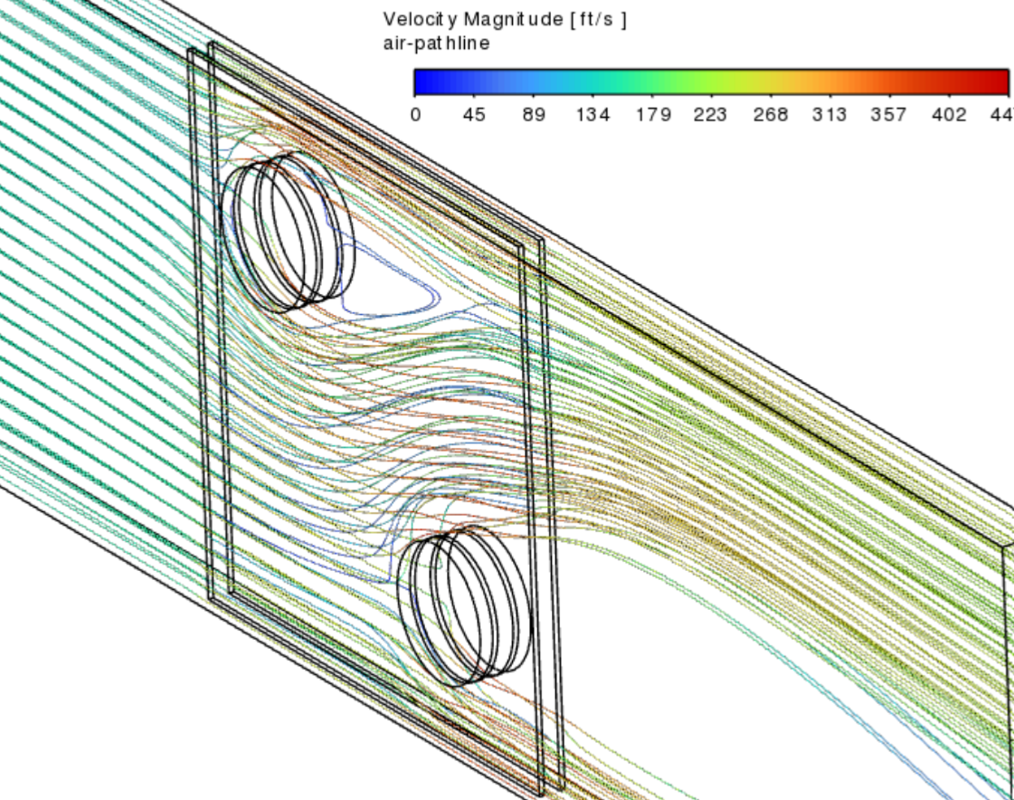
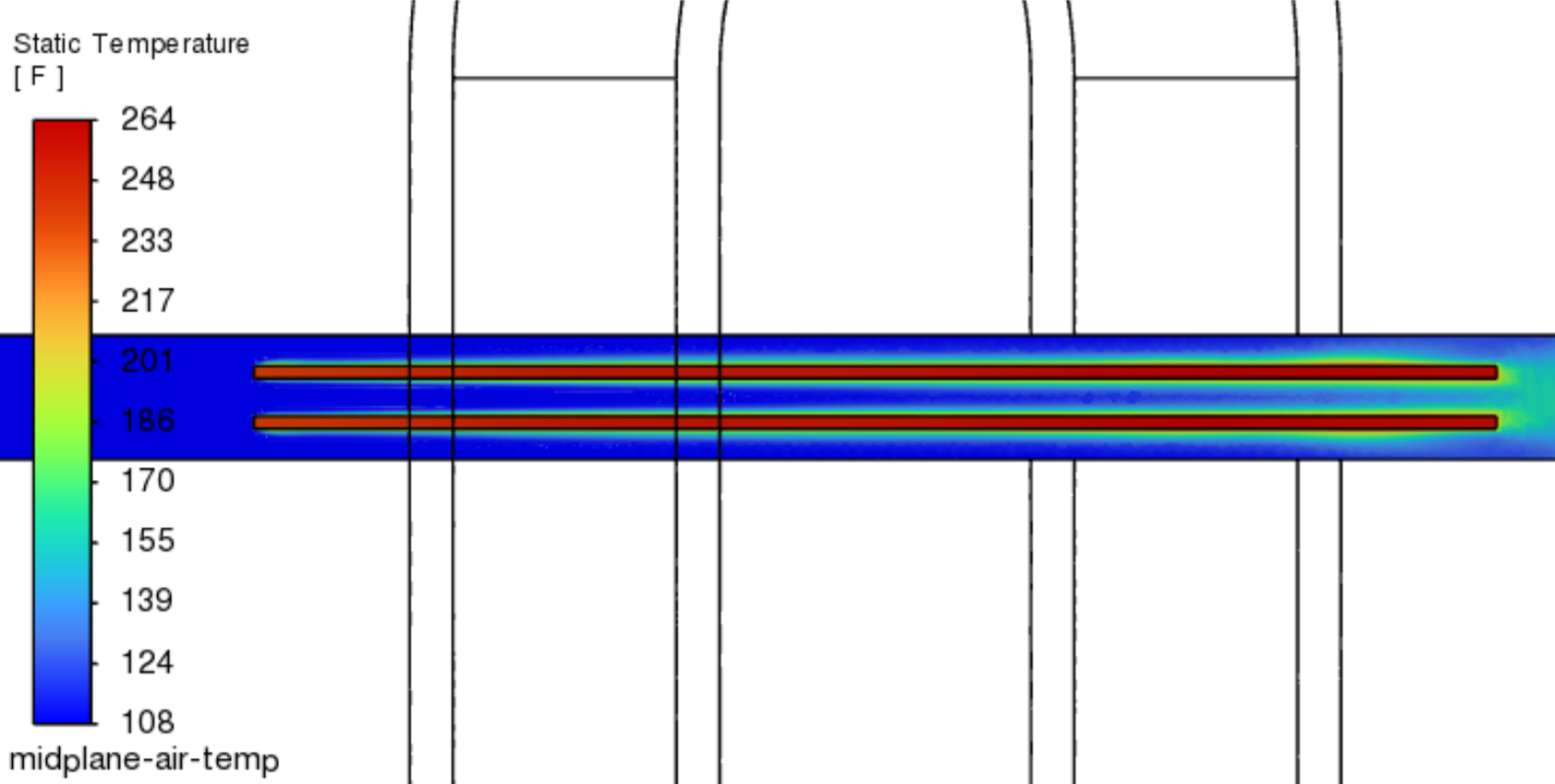
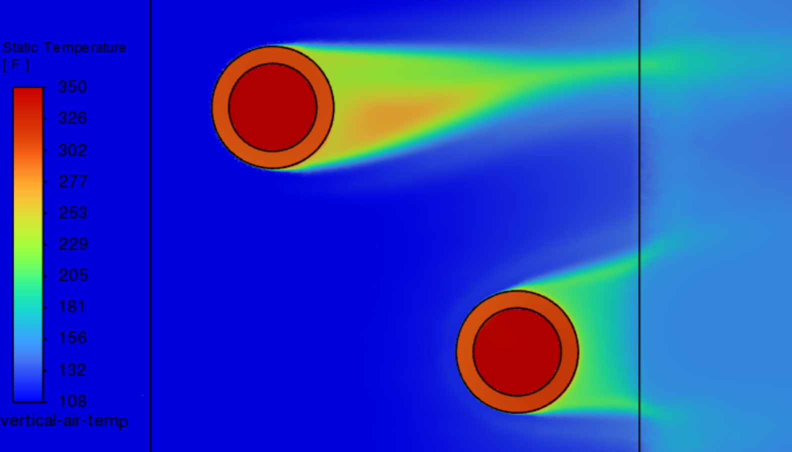
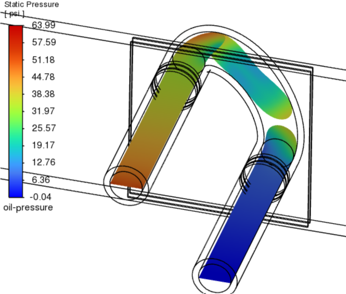
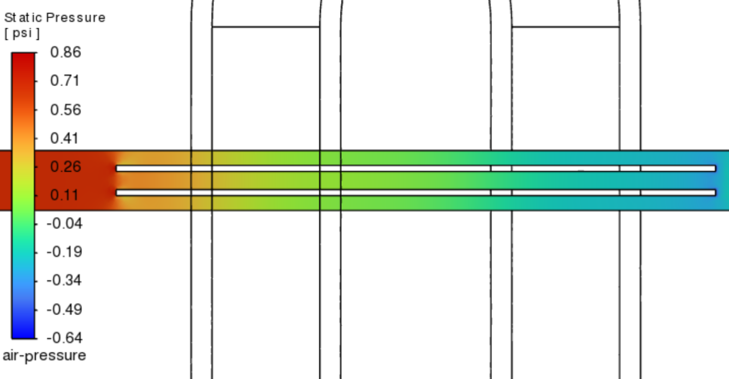
We developed 3 CFD simulations in developing our heat exchanger design: one for the air duct to the heat exchanger, one for a single tube segment with two fins, and one for a simplified tube bank with two fins. The air duct simulation verified the heat exchanger entrance velocity and the pressure drop across the duct. The single tube segment simulation verified that the fin thickness and the distance between adjacent fins were set such that the thermal boundary layers would converge at the end of the modeled fin. The double tube segment simulation verified that the distance between tube rows was set such that the air from one row would not significantly thermally interact with the air the next row. This simulation also verified that the calculation method for determining the pressure drop for the air and oil in the design hand calculations was appropriate, accounting for the oil pressure drop across the tube bend.

The air boundaries were all modeled as symmetry boundary conditions aside from the leftmost and rightmost walls, which had mass flow inlet and pressure outlet boundary conditions, respectively. The oil in the tube was modeled similarly with one mass flow inlet and one pressure outlet boundary condition.

All simulations used the k-omega SST turbulence model; this model captured the near-wall behavior near the fins well while also capturing the fully turbulent free-stream flow in and around the heat exchanger tube bank. All simulations ran for 1,000 iterations in steady state using a pressure-based solver with the SIMPLE algorithm used for pressure/velocity coupling.

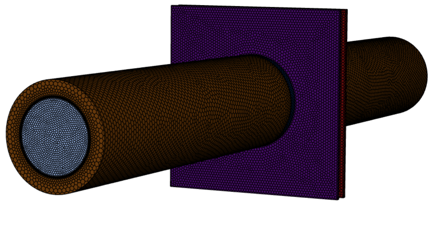
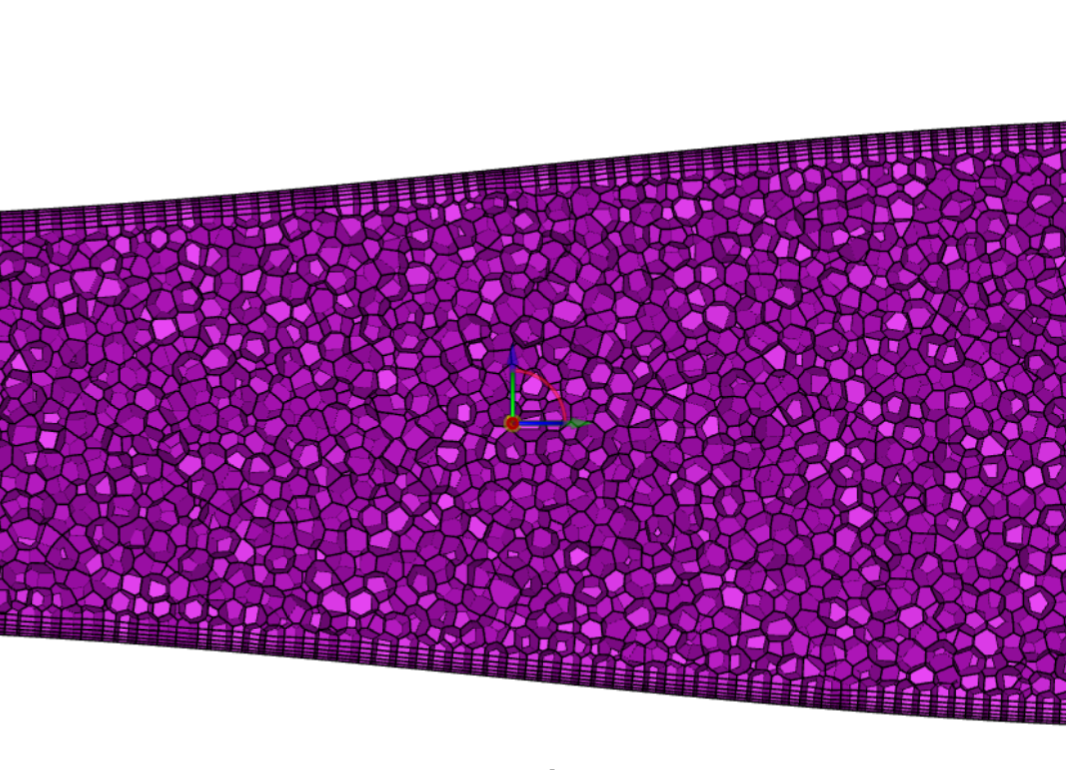
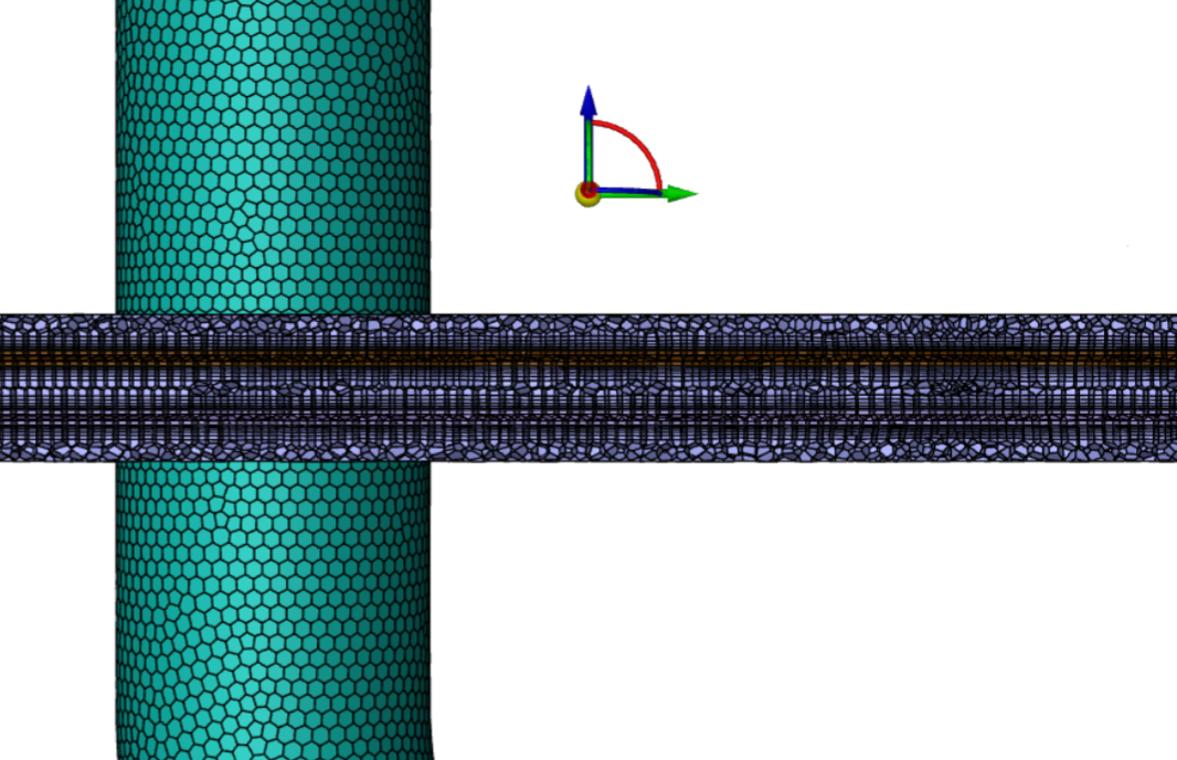
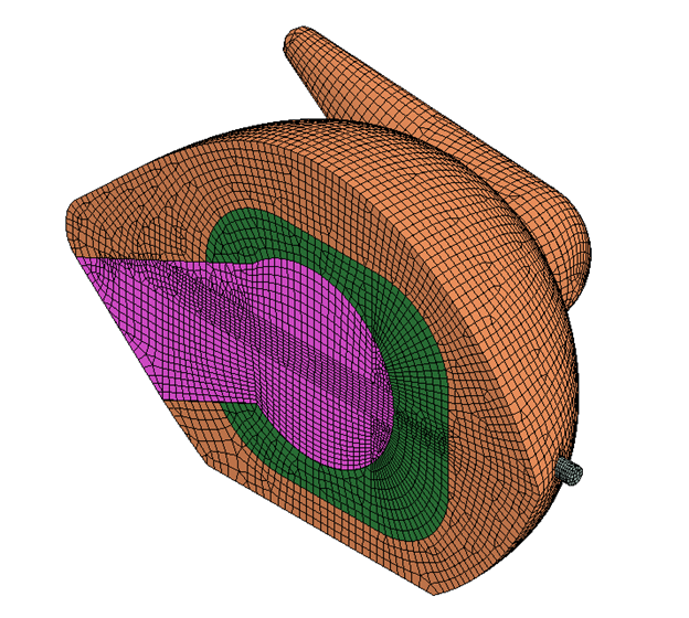
We used polyhedral meshing in ANSYS Fluent to model both the air and solid copper for each simulation. All fluid regions had five-element tall boundary layers and all solid regions had one-element tall boundary layers to properly capture conjugate heat transfer between the materials and to maintain a wall y+ below 1 at the fins and along the tube/duct length.

Results

Our model results closely matched the hand calculations (maximum ~15% difference) and proved that the assumptions made in these calculations were justified. Results indicated that an 8” x 8” x 8” heat exchanger weighing 24.33 lbs was sufficient to cool the engine oil to the required 195°F criterion while maintaining a realistic oil and air pressure drop and maintaining a manufacturable design.


A detailed 55-page report further covering the operating metrics, design hand calculations, all CFD simulations, and fully dimensioned design drawings can be found here.