Axial Flow Compressor Design and CFD Analysis

Axial Flow Compressor Design and CFD Analysis

Timeline:
Spring 2018

Tools used:
ANSYS Fluent, SolidWorks, Excel

Background

For the final project in Cooper Union’s Computational Fluid Dynamics (CFD) course, students were divided into 4-person teams tasked with designing an axial flow compressor under specified pressure ratio, size, and speed constraints. The objective was to minimize the power consumption of the compressor while maintaining an outer diameter between 4 and 6 feet, operating at a rotational speed under 65,000 RPM, and providing a minimum pressure ratio of 20:1 at a design altitude of 37,000 feet. No constraints were placed on rotor and stator geometry, material strength, material compatibility, and manufacturing methods and costs. We performed transient CFD simulations and validation hand calculations to achieve this design task.
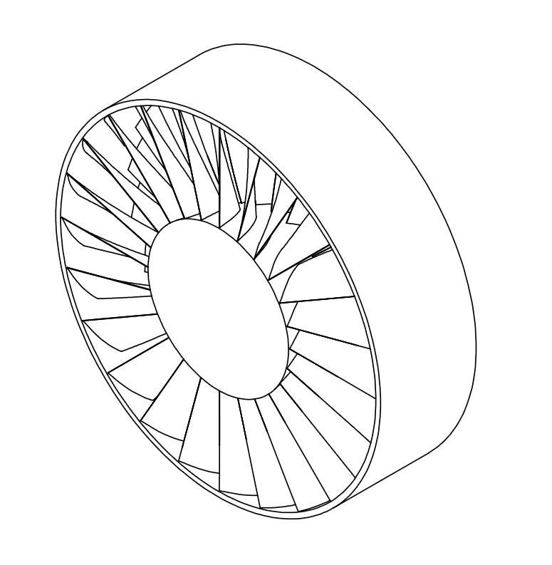
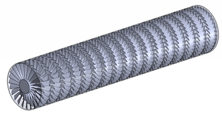
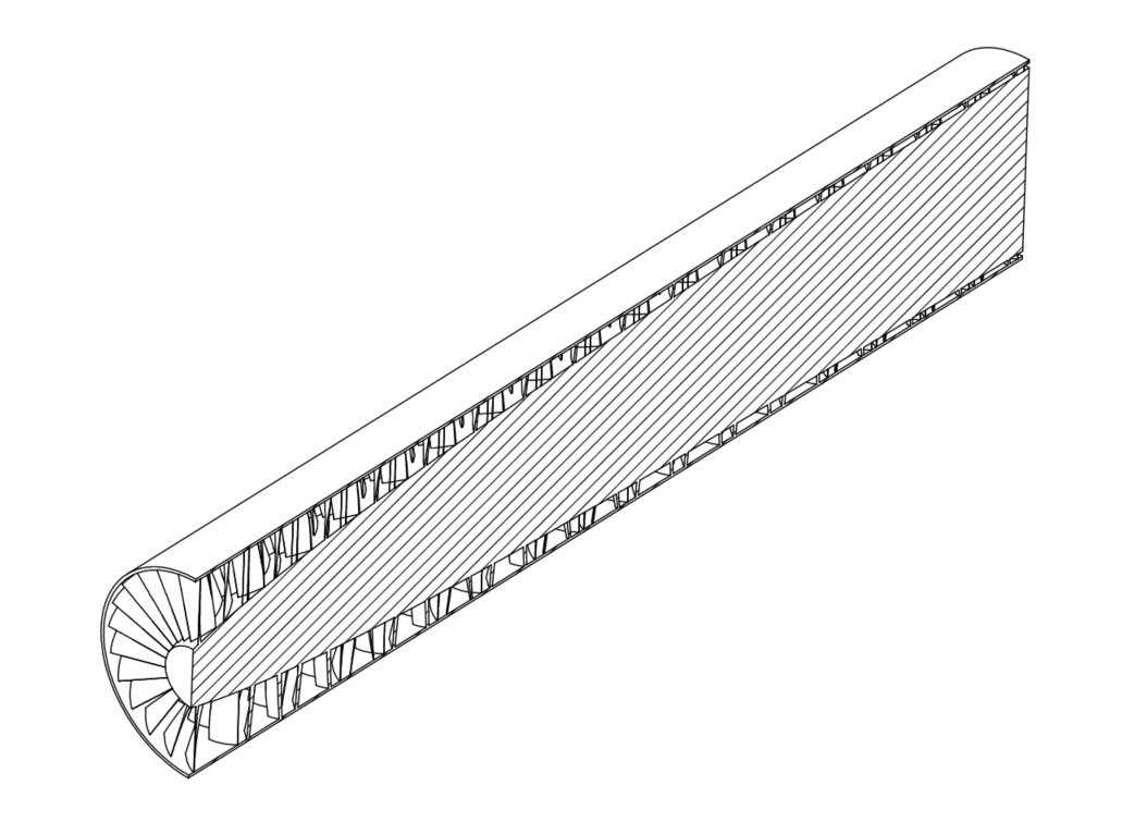
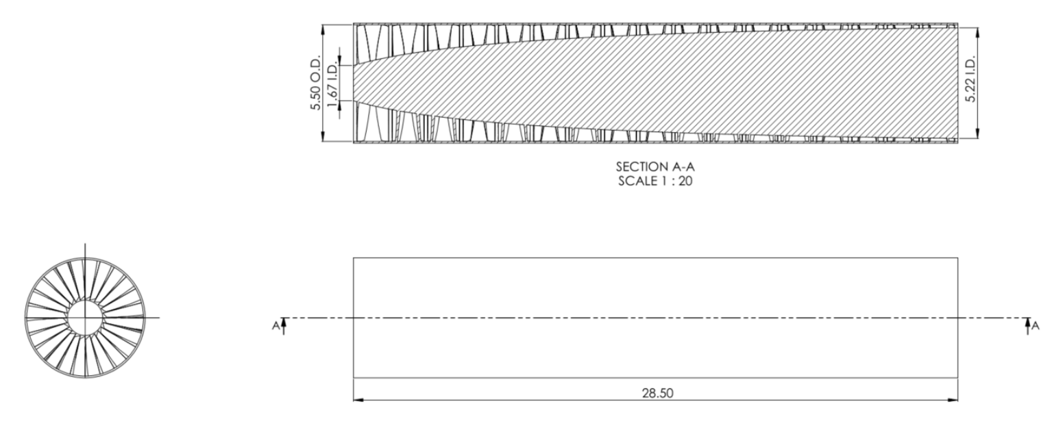
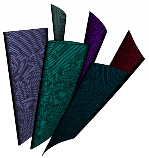
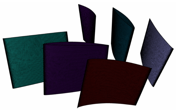
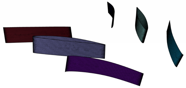
Image related to paragraph 0 Compressor overall geometry.

Each team was provided with the same design limitations, performance criteria, and design goal. The complete assignment can be found here.

Design Concept

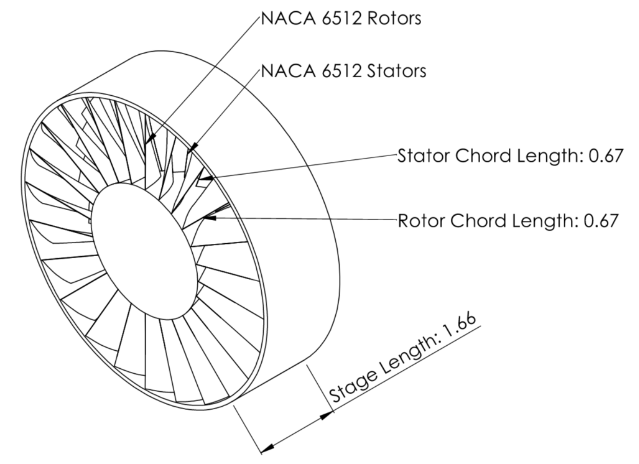
Based on existing axial flow compressor designs and preliminary hand calculations, we chose to design a 17-stage subsonic compressor with a compression ratio of 1.2:1 per stage, a blade solidity of 1.4, and a constant chord length of 8 inches for both rotor and stator blades. The outer diameter of the compressor remained constant at 5.50 feet. The rotor hub followed a square root growth profile derived using mass flow conservation and isentropic airflow properties, varying from 1.67 feet to 5.18 feet in diameter. The number of blades increased from 24 to 36 across the compressor to maintain constant blade solidity. The rotor operates at a constant speed of 6,000 RPM.

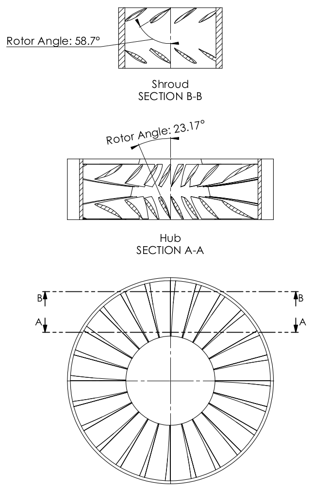
We used NACA 6512 compressor blades due to their relative insensitivity to airflow conditions at high angles of attack. Given their stall angle of roughly 15 degrees, we designed the blades to ensure no portion of the blade would stall at any distance from the compressor hub. Because the velocity of the rotor tips was greater than that of the rotor roots, the blades twisted continuously from root to tip. There was a constant angle of twist for each stage; the blades gradually approached the tip angle as the rotor hub approached the compressor shroud.

Design Hand Calculations

The design hand calculations utilized basic axial flow compressor theory and velocity triangles to determine the specific enthalpy rise, consumed power, and efficiency of each stage. We used the median blade height and angle to calculate these parameters at each stage as a rough approximation. Each assumption was validated and refined using detailed CFD simulations. This approach allowed us to assess the impact of geometric and operational parameter changes on overall power consumption, simplifying the design process into a multidimensional optimization problem. We used Excel to organize our calculations, leveraging Excel’s Solver tool for straightforward parameter optimization.

CFD Simulation Setup and Mesh

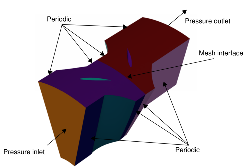
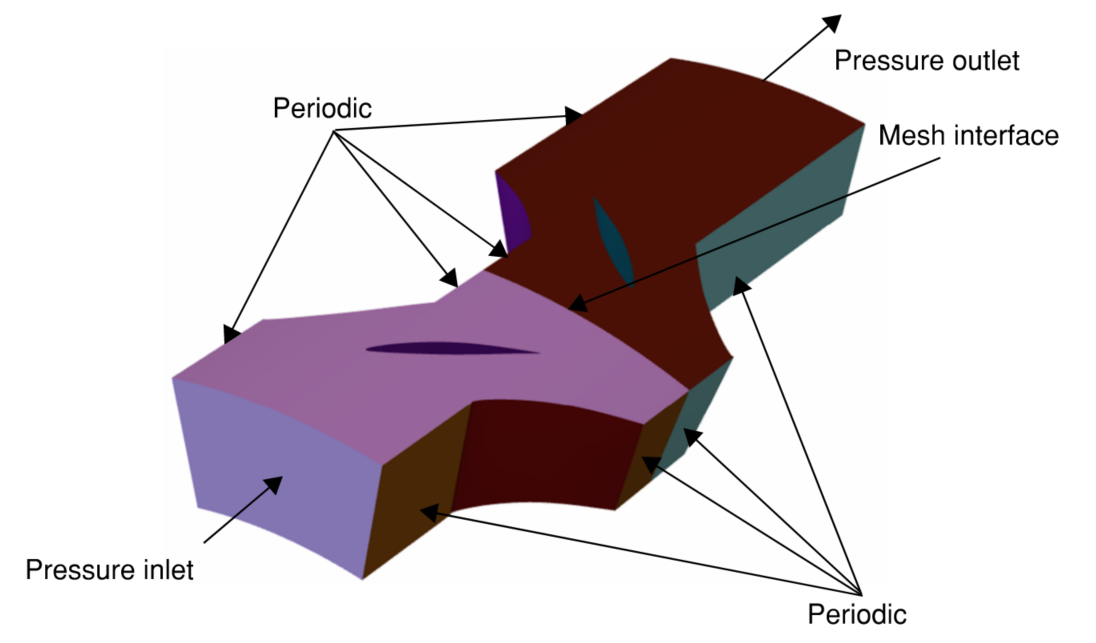
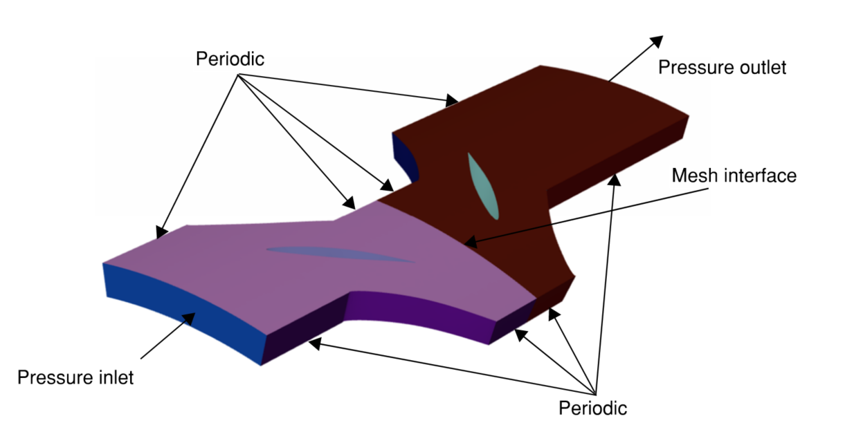
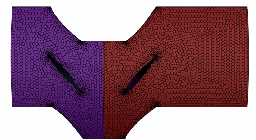
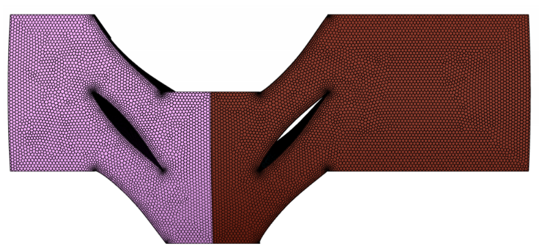
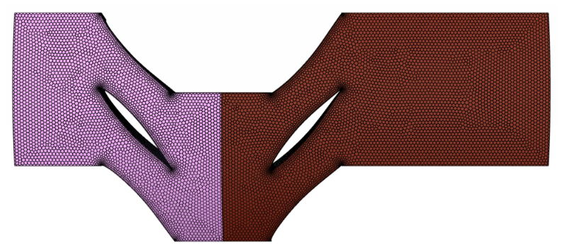
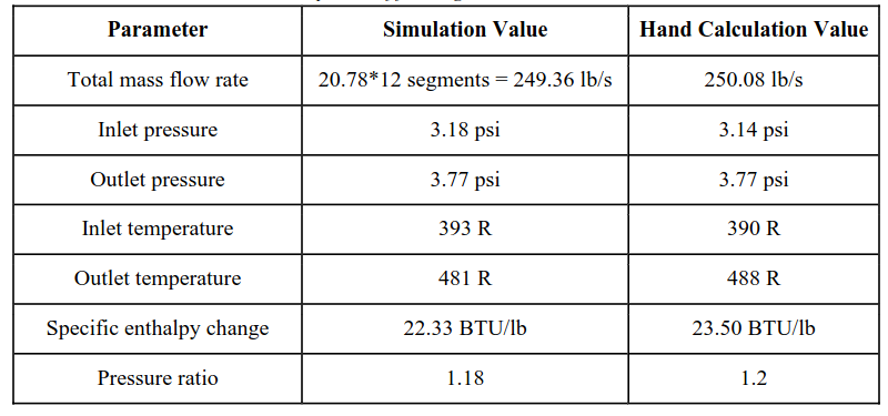
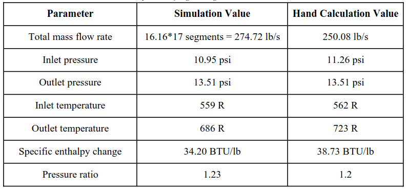
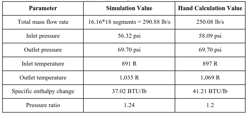
We developed 3 transient CFD simulations in developing our compressor design: one for the first stage, one for the eighth stage, and one for the final stage. These simulations were used to compare the simulated total mass flow rate, inlet and outlet pressures, inlet and outlet temperatures, and specific enthalpy rises to our hand calculations to ensure results are fully validated. Each stage’s geometry consisted of 3 rotor blades, 3 stator blades, and inlet and outlet ducts to account for flow entrance length and to mitigate flow reversal, respectively.

The geometry for each stage was split into 2 zones: a rotor cell zone and a stator cell zone. The entrance to the inlet duct and the exit to the outlet duct are set as a pressure inlet and a pressure outlet, respectively. Rotational periodic boundary conditions were applied to the sides of the model to simulate the entire stage. A mesh interface with periodic repeats was used at the interface between the rotor and stator. All other boundaries were treated as non-slip walls. The rotor cell zone was given a rotational speed of 6,000 RPM while the stator cell zone remained stationary.

All simulations used the realizable k-epsilon turbulence model with scalable wall functions; this model captured both near-wall behavior and gross flow behavior without the concern of having too low of a wall y+ along the blade walls for the turbulence model used. All simulations ran for 720 time steps with 10 iterations per time step with a time step of 41.67 µs using a pressure-based solver with the Coupled algorithm used for pressure/velocity coupling.

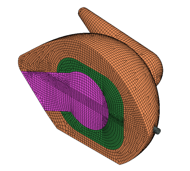
We used polyhedral meshing in ANSYS Fluent to model the air for each simulation. All near-blade regions had five-element tall boundary layers.

Results

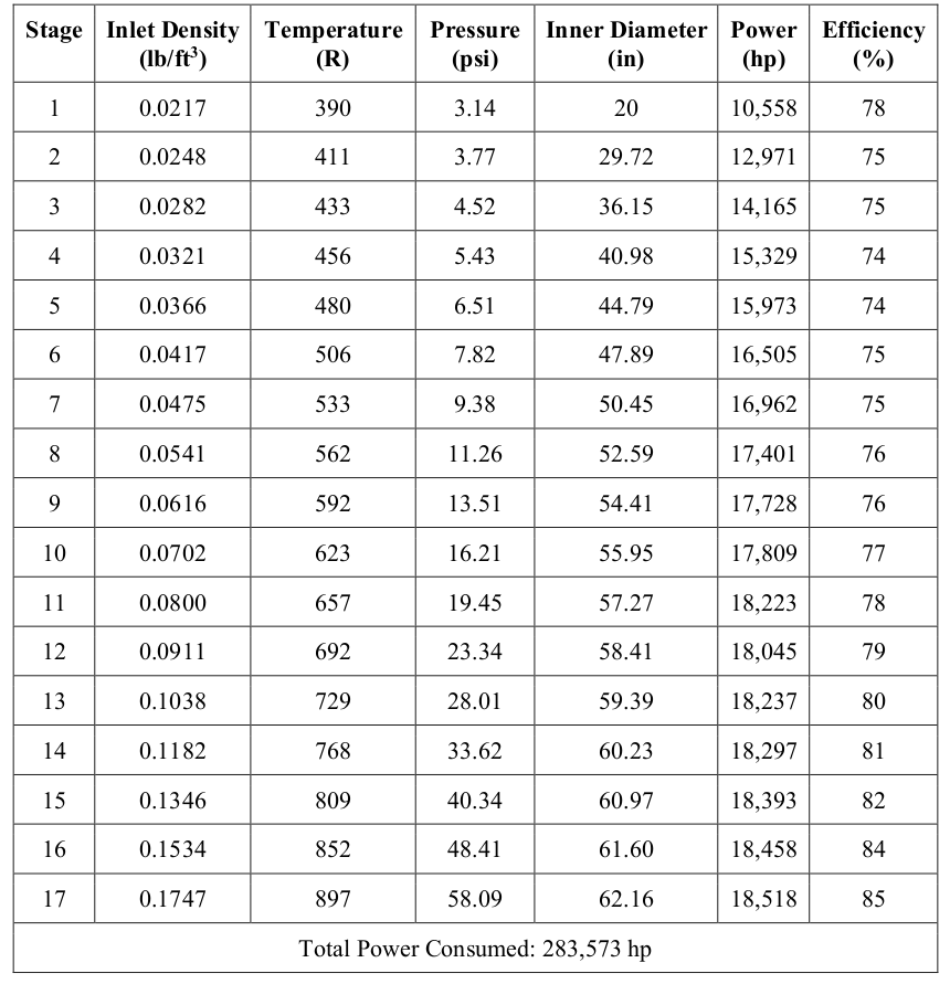
Our model results closely matched the design hand calculations (maximum ~5% difference) and proved that the assumptions made in these calculations were justified. Results indicated that our compressor consumed approximately 283,573 horsepower at 37,000 feet above ground level with an average isentropic efficiency of 78% while maintaining an overall pressure ratio of at least 20:1.


A detailed 46-page report further covering the operating metrics, design hand calculations, all CFD simulations, and fully dimensioned design drawings can be found here.