REU - PIV/CFD Study of Tumble Generation in a Pent-Roof Internal Combustion Engine

REU - PIV/CFD Study of Tumble Generation in a Pent-Roof Internal Combustion Engine

Timeline:
Summer 2018

Tools used:
Particle image velocimetry, SolidWorks, MATLAB, CONVERGE CFD, Tecplot

Background

The goal of this project was to use a fully-validated CFD model to predict airflow patterns and levels of in-cylinder tumble (flow rotation about an axis perpendicular to the cylinder axis) in a 2.4-liter Chrysler Cirrus engine cylinder when the intake port is modified in the CFD model. To validate this model, I used particle image velocimetry (PIV) on a portion of an acrylic cylinder to visualize airflow when the intake valves were set to fixed valve lift to valve diameter ratios. Upon obtaining airflow velocity vector profiles using both PIV and CFD, I directly compared the overall error in vector magnitude and angle using root mean squared error and cosine similarity, respectively. Additionally, I calculated the nondimensional tumble number (the ratio of total angular momentum in the cylinder to the maximum total angular momentum in the cylinder) for both PIV and CFD results for comparison.
This project was part of a Research Experience for Undergraduates (REU) under the supervision of Dr. Paul Puzinauskas and PhD student Alex Voris.

Experimental Model and Results

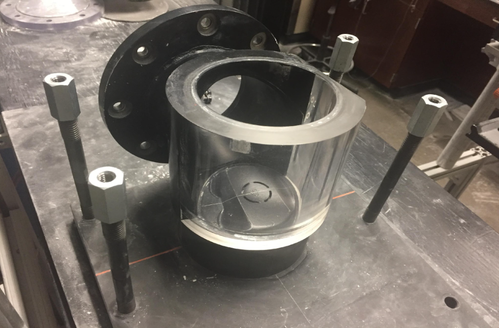
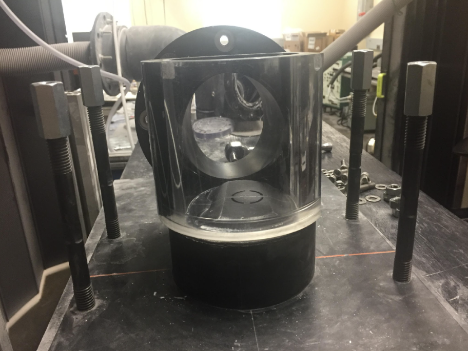
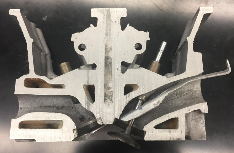
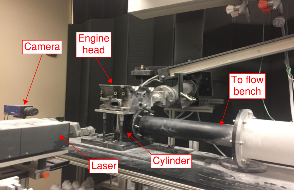
The PIV setup consisted of a CCD camera, a Nd:YAG pulsed laser, a SuperFlow SF-1020 flow bench, an engine head with the exhaust ports sealed, and an acrylic cylinder with the side exposed to the pulsed laser shaved flat to mitigate unwanted scattering. The camera was synchronized with the laser to capture images of the velocity field. The flow was seeded with talcum powder particulates; these particulates were tracked to obtain velocity vectors as a function of position using LaVision’s DaVis 7.2 PIV software. All tests were performed under a constant pressure differential of 25 inches of water.


I used a multi-pass iteration scheme (a 64x64 pixel interrogation window followed by a 32x32 pixel interrogation window) to increase resolution of the computed vector field. I applied a median filter to the interrogation area to eliminate vectors with a difference of greater than 3 RMS of neighboring vectors. Additionally, I applied a smoothing filter to the interrogation area to eliminate high frequency noise from each vector field.

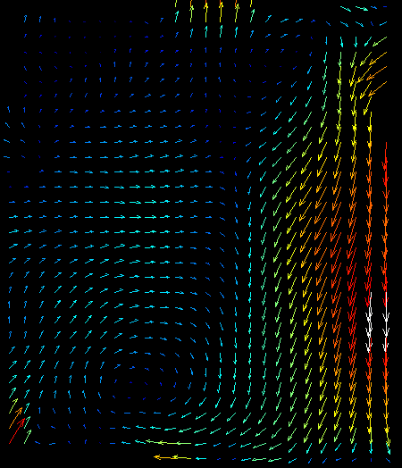
For each test, I took 50 dual images with the CCD camera and cross-correlated them with one another to obtain the velocity fields. Using the smoothing filter, these images were averaged and a single image encompassing the entire experiment was produced for each lift to diameter (L/D) ratio.

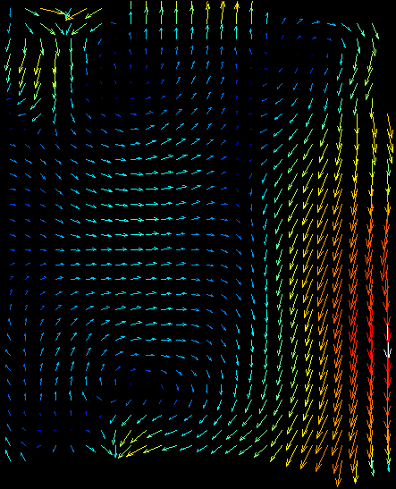
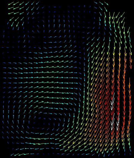
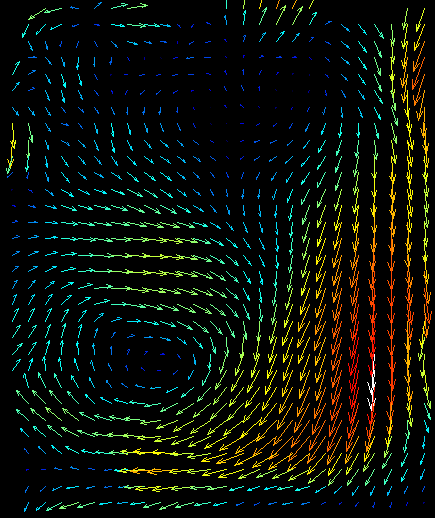
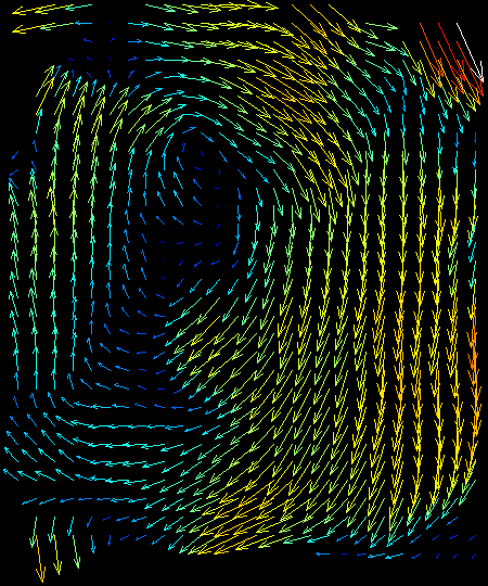
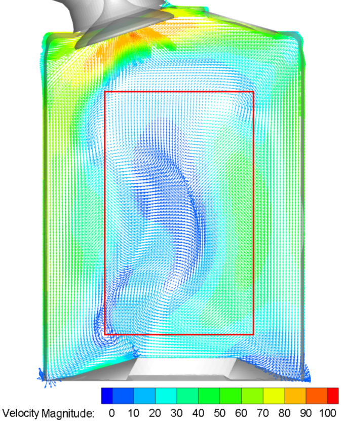
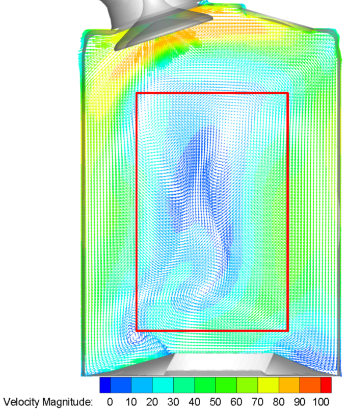
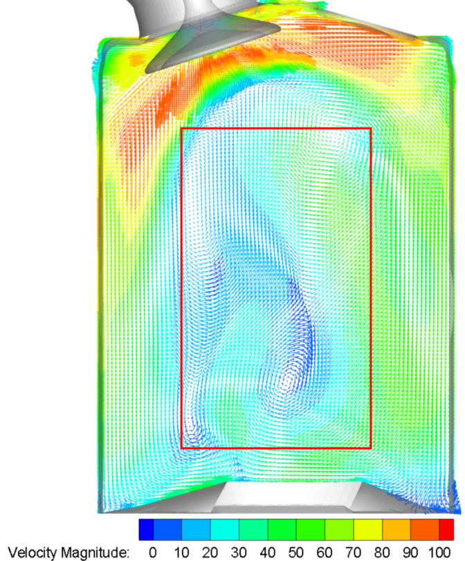
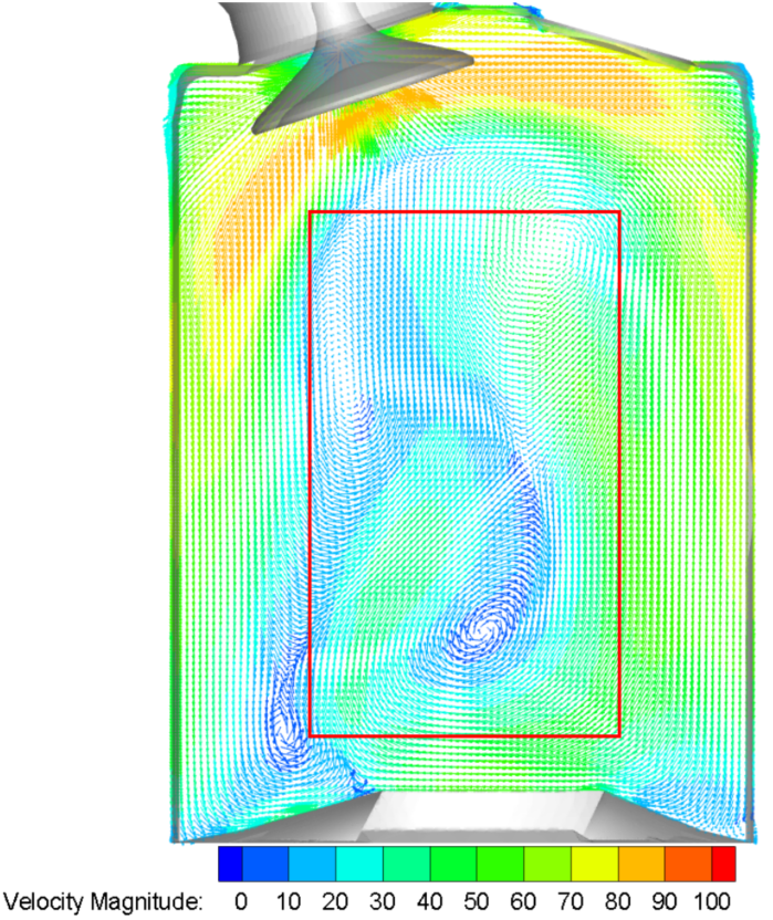
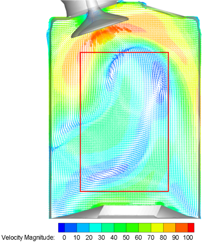
Results indicate that as the valve lift increases, the generated vortices become more coherent and combine to better resemble solid body rotation. As the vortices combine, the center of rotation shifts upward in the cylinder.

Analytical Model and Results

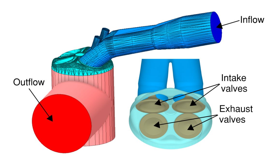
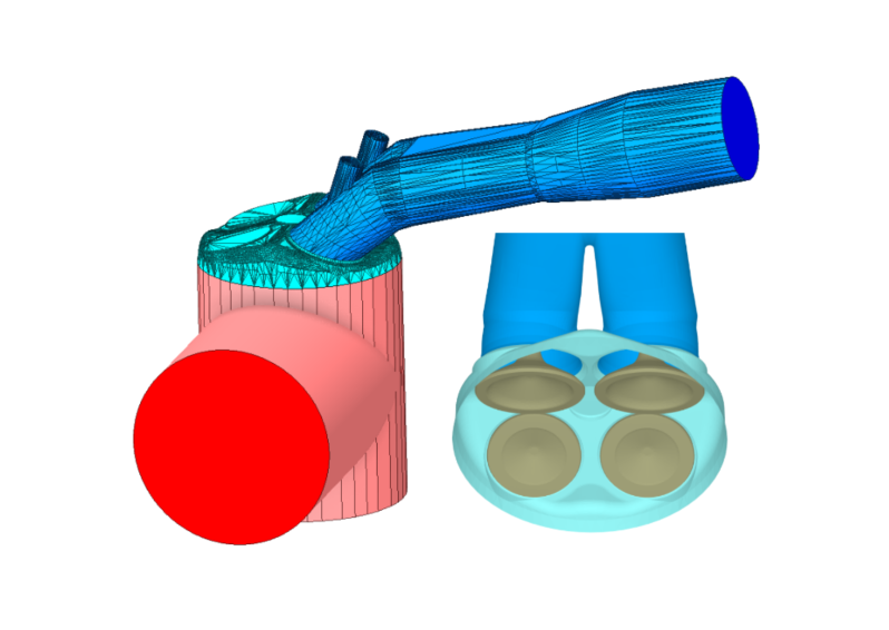
I recreated the interior of the cylinder and a portion of the intake and exhaust geometry in SolidWorks. The inflow and outflow regions were extended to account for entrance lengths and to prevent backflow.

I used CONVERGE CFD to simulate the inflow of air into the cylinder with the same constant lift values as those specified in the PIV experiment and with the cylinder fixed at bottom dead center. I used a Cartesian cut-cell mesh with automatic mesh refinement based on the velocity gradient. All simulations used the k-omega SST turbulence model; this model captured the near-wall behavior near the cylinder wall well while also capturing the fully turbulent free-stream flow within the cylinder.

All boundaries were treated as walls aside from the inflow and outflow, which were treated as a pressure inlet and a pressure outlet, respectively. All simulations ran for 10,000 iterations in steady state using the Dense Memory Cluster provided by the Alabama Supercomputer Authority. All resulting velocity fields and animations were obtained using Tecplot, a CFD post-processing program.

Results indicate that, similarly to the PIV experiment described above, the increased valve lift increases the size and strength of the vortices while shifting their location farther up in the cylinder.

Result Comparison

A comparison between PIV and CFD results indicates a very close visual similarity between results within the captured region. Note that the PIV results did not capture results throughout the entire cylinder; the region of interest is highlighted in a red box for clarity.

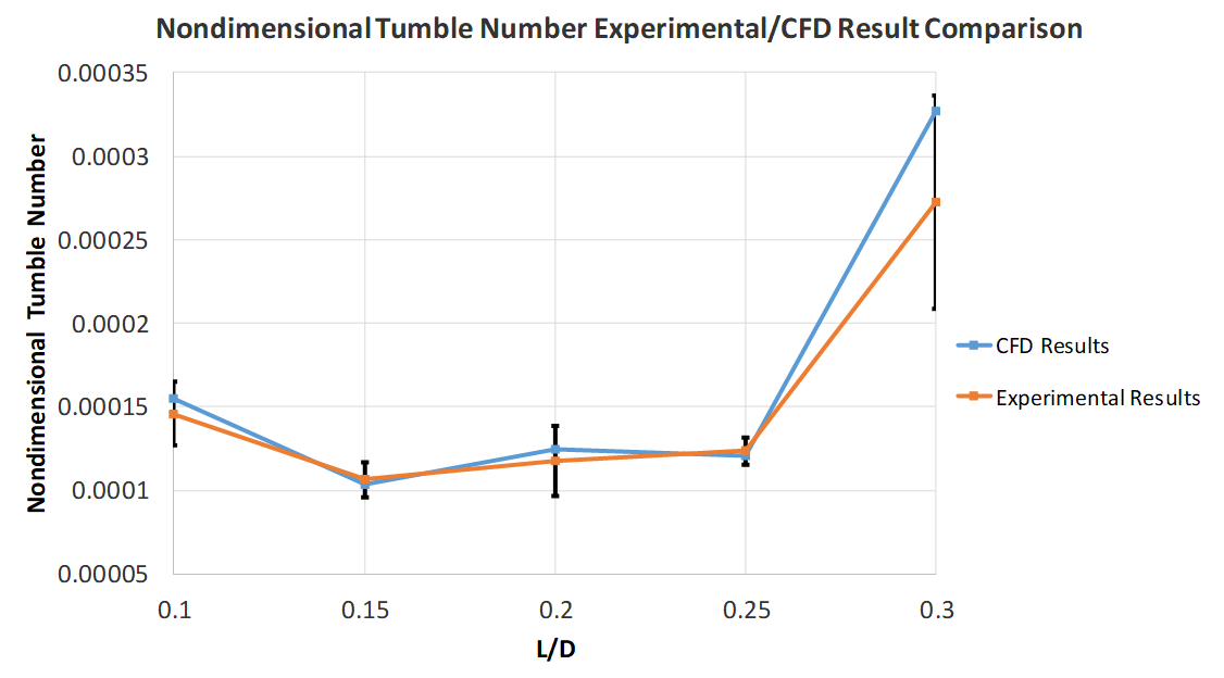
Quantitatively, the nondimensional tumble number was calculated for both PIV and CFD results. Comparison indicates very close agreement within a 95% confidence interval.

Additionally, I directly compared the overall error in vector magnitude and angle using root mean squared error and cosine similarity, respectively. Results indicate close agreement between direction and magnitude for both PIV and CFD results.

I presented these results with a poster at the 71st annual meeting of the APS Division of Fluid Dynamics.